
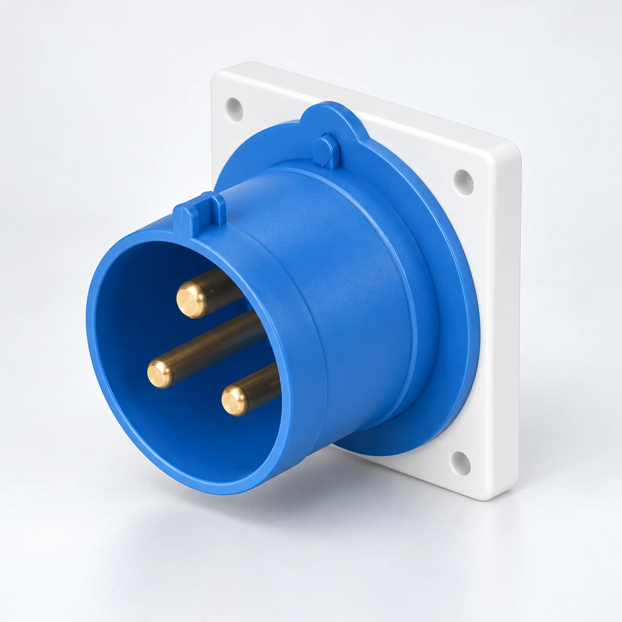
IP44 Conectores para electrodomésticos industriales
YOCL ELECTRIC IP44 entradas para aparatos industriales en versiones 16 A y 32 A. Elija contactos 2P+E, 3P+E o 3P+N+E, montaje en panel o en superficie y la capacidad de conductor correspondiente en la tabla de modelos.
Descripción general
Las entradas para aparatos industriales YOCL ELECTRIC IP44 proporcionan una conexión de alimentación macho en maquinaria, equipos de distribución y carcasas de equipos. La familia cubre versiones 16 A y 32 A en configuraciones 2P+E, 3P+E y 3P+N+E. Las entradas rectas para panel y los diseños de entrada en superficie cerrados se agrupan aquí para que la interfaz de suministro pueda seleccionarse junto con su disposición de montaje. Un conector de cable hembra a juego proporciona la conexión de cable desmontable.
Características
- Versiones IP44 para conexiones industriales protegidas contra salpicaduras.
- Diseños rectos para panel en carcasas estándar y K, además de diseños en superficie con una cara de conector en ángulo.
- Opciones 16 A y 32 A con rangos de conductor indicados para cada modelo.
- Posición de contacto de tierra 6h en los modelos listados.
- Las carcasas de contacto azules y rojas distinguen las configuraciones eléctricas listadas.
Especificaciones técnicas
| Parámetro | Especificación |
|---|---|
| Marca | YOCL ELÉCTRICO |
| Tipo de producto | Entrada para aparatos industriales / entrada macho para equipos |
| Grado de protección | IP44 |
| Opciones de corriente nominal | 16 A, 32 A |
| Configuraciones de contacto | 2P+E; 3P+E; 3P+N+E |
| Posición de contacto a tierra | 6h |
| Montaje | Montaje en panel o montaje superficial con carcasa, según el modelo |
| Interfaz de cable de acoplamiento | Conector de cable industrial hembra a juego |
| Capacidad del conductor | Específico del modelo; consulte la tabla de selección |
Selección de modelo
| Modelo | Montaje / carcasa | Corriente (A) | Contactos | Voltaje | Posición de tierra | Carcasa de contacto | Conductor cross-section (mm²) |
|---|---|---|---|---|---|---|---|
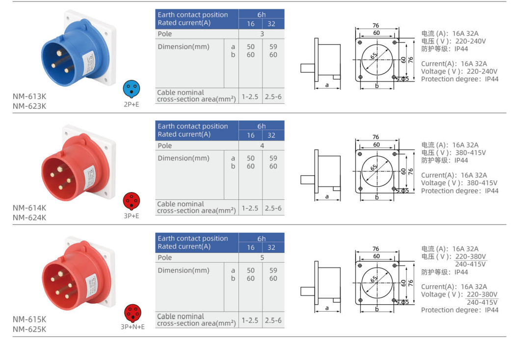
| NM-613K | Straight panel inlet, K housing | 16 | 2P+E | 220–240 V | 6h | Azul | 1–2.5 |
| NM-623K | Straight panel inlet, K housing | 32 | 2P+E | 220–240 V | 6h | Azul | 2.5–6 |
| NM-614K | Straight panel inlet, K housing | 16 | 3P+E | 380–415 V | 6h | Rojo | 1–2.5 |
| NM-624K | Straight panel inlet, K housing | 32 | 3P+E | 380–415 V | 6h | Rojo | 2.5–6 |
| NM-615K | Straight panel inlet, K housing | 16 | 3P+N+E | 220–380 V / 240–415 V | 6h | Rojo | 1–2.5 |
| NM-625K | Straight panel inlet, K housing | 32 | 3P+N+E | 220–380 V / 240–415 V | 6h | Rojo | 2.5–6 |
| NM-613 | Straight panel inlet | 16 | 2P+E | 220–240 V | 6h | Azul | 1–2.5 |
| NM-623 | Straight panel inlet | 32 | 2P+E | 220–240 V | 6h | Azul | 2.5–6 |
| NM-614 | Straight panel inlet | 16 | 3P+E | 380–415 V | 6h | Rojo | 1–2.5 |
| NM-624 | Straight panel inlet | 32 | 3P+E | 380–415 V | 6h | Rojo | 2.5–6 |
| NM-615 | Straight panel inlet | 16 | 3P+N+E | 220–380 V / 240–415 V | 6h | Rojo | 1–2.5 |
| NM-625 | Straight panel inlet | 32 | 3P+N+E | 220–380 V / 240–415 V | 6h | Rojo | 2.5–6 |
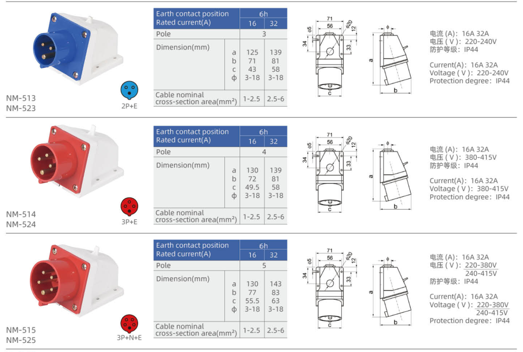
| NM-513 | Surface inlet with angled face | 16 | 2P+E | 220–240 V | 6h | Azul | 1–2.5 |
| NM-523 | Surface inlet with angled face | 32 | 2P+E | 220–240 V | 6h | Azul | 2.5–6 |
| NM-514 | Surface inlet with angled face | 16 | 3P+E | 380–415 V | 6h | Rojo | 1–2.5 |
| NM-524 | Surface inlet with angled face | 32 | 3P+E | 380–415 V | 6h | Rojo | 2.5–6 |
| NM-515 | Surface inlet with angled face | 16 | 3P+N+E | 220–380 V / 240–415 V | 6h | Rojo | 1–2.5 |
| NM-525 | Surface inlet with angled face | 32 | 3P+N+E | 220–380 V / 240–415 V | 6h | Rojo | 2.5–6 |
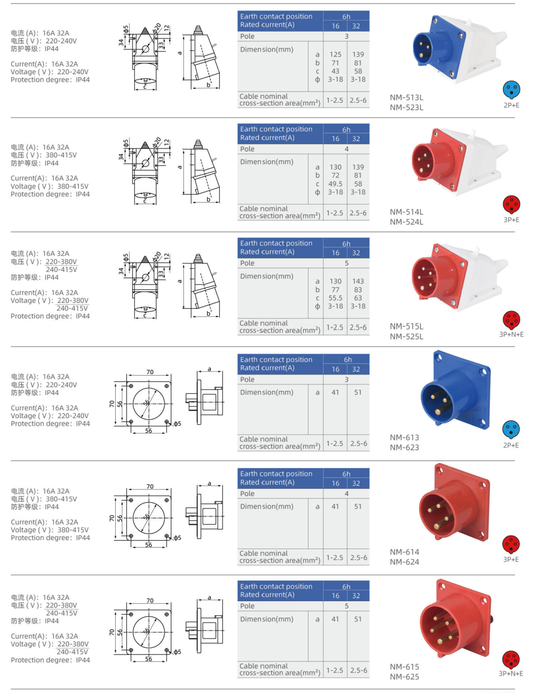
| NM-513L | Surface inlet with angled face — L housing | 16 | 2P+E | 220–240 V | 6h | Azul | 1–2.5 |
| NM-523L | Surface inlet with angled face — L housing | 32 | 2P+E | 220–240 V | 6h | Azul | 2.5–6 |
| NM-514L | Surface inlet with angled face — L housing | 16 | 3P+E | 380–415 V | 6h | Rojo | 1–2.5 |
| NM-524L | Surface inlet with angled face — L housing | 32 | 3P+E | 380–415 V | 6h | Rojo | 2.5–6 |
| NM-515L | Surface inlet with angled face — L housing | 16 | 3P+N+E | 220–380 V / 240–415 V | 6h | Rojo | 1–2.5 |
| NM-525L | Surface inlet with angled face — L housing | 32 | 3P+N+E | 220–380 V / 240–415 V | 6h | Rojo | 2.5–6 |
P denotes a phase contact, N neutral and E protective earth. A dash means that no voltage is assigned in this selection table.
Dimensión
| Modelo | Lettered outline dimensions (mm) | Fixed mounting geometry |
|---|---|---|
| NM-613K | a=50, b=60 | Flange width × height (mm): 76 × 76; Fixing centres (mm): 60 × 60; Panel opening diameter (mm): 65; Fixing hole diameter (mm): 5 |
| NM-623K | a=59, b=60 | Flange width × height (mm): 76 × 76; Fixing centres (mm): 60 × 60; Panel opening diameter (mm): 65; Fixing hole diameter (mm): 5 |
| NM-614K | a=50, b=60 | Flange width × height (mm): 76 × 76; Fixing centres (mm): 60 × 60; Panel opening diameter (mm): 65; Fixing hole diameter (mm): 5 |
| NM-624K | a=59, b=60 | Flange width × height (mm): 76 × 76; Fixing centres (mm): 60 × 60; Panel opening diameter (mm): 65; Fixing hole diameter (mm): 5 |
| NM-615K | a=50, b=60 | Flange width × height (mm): 76 × 76; Fixing centres (mm): 60 × 60; Panel opening diameter (mm): 65; Fixing hole diameter (mm): 5 |
| NM-625K | a=59, b=60 | Flange width × height (mm): 76 × 76; Fixing centres (mm): 60 × 60; Panel opening diameter (mm): 65; Fixing hole diameter (mm): 5 |
| NM-613 | a=41 | Flange width × height (mm): 70 × 70; Fixing centres (mm): 56 × 56; Panel opening diameter (mm): 46; Fixing hole diameter (mm): 5 |
| NM-623 | a=51 | Flange width × height (mm): 70 × 70; Fixing centres (mm): 56 × 56; Panel opening diameter (mm): 46; Fixing hole diameter (mm): 5 |
| NM-614 | a=41 | Flange width × height (mm): 70 × 70; Fixing centres (mm): 56 × 56; Panel opening diameter (mm): 46; Fixing hole diameter (mm): 5 |
| NM-624 | a=51 | Flange width × height (mm): 70 × 70; Fixing centres (mm): 56 × 56; Panel opening diameter (mm): 46; Fixing hole diameter (mm): 5 |
| NM-615 | a=41 | Flange width × height (mm): 70 × 70; Fixing centres (mm): 56 × 56; Panel opening diameter (mm): 46; Fixing hole diameter (mm): 5 |
| NM-625 | a=51 | Flange width × height (mm): 70 × 70; Fixing centres (mm): 56 × 56; Panel opening diameter (mm): 46; Fixing hole diameter (mm): 5 |
| NM-513 | a=125, b=71, c=43, Φ=3–18 | — |
| NM-523 | a=139, b=81, c=58, Φ=3–18 | — |
| NM-514 | a=130, b=72, c=49.5, Φ=3–18 | — |
| NM-524 | a=139, b=81, c=58, Φ=3–18 | — |
| NM-515 | a=130, b=77, c=55.5, Φ=3–18 | — |
| NM-525 | a=143, b=83, c=63, Φ=3–18 | — |
| NM-513L | a=125, b=71, c=43, Φ=3–18 | — |
| NM-523L | a=139, b=81, c=58, Φ=3–18 | — |
| NM-514L | a=130, b=72, c=49.5, Φ=3–18 | — |
| NM-524L | a=139, b=81, c=58, Φ=3–18 | — |
| NM-515L | a=130, b=77, c=55.5, Φ=3–18 | — |
| NM-525L | a=143, b=83, c=63, Φ=3–18 | — |
Use the lettered dimensions with the matching inlet outline. Flange geometry and housing size differ between body versions; select the complete model code when checking installation space.
Selección de conexión
Match rated current, contact configuration, voltage and earth-contact position at both sides of the connection. Select panel or surface mounting before comparing the housing dimensions. The IP rating applies to the correctly assembled connection with its compatible mating interface; maintain the specified sealing and closure arrangement.
Información de pedido
Send YOCL ELECTRIC the full model code, required quantity, supply voltage, contact configuration and installation arrangement. Include conductor cross-section and the mating cable connector when requesting a complete equipment power connection.