
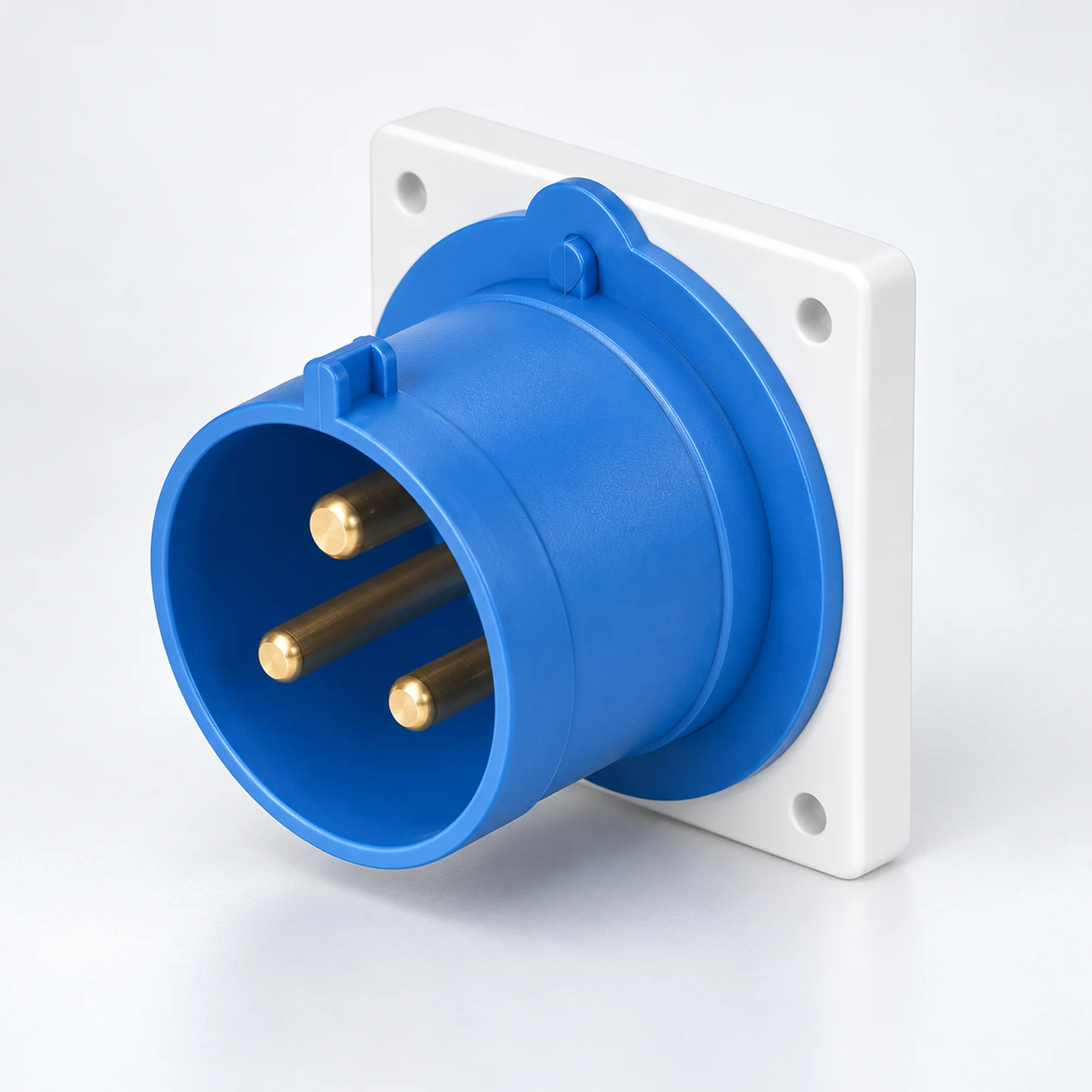
IP44 Industrial Appliance Inlets
YOCL ELECTRIC IP44 industrial appliance inlets in 16 A and 32 A versions. Choose 2P+E, 3P+E or 3P+N+E contacts, panel or surface mounting and the matching conductor capacity from the model table.
Overview
YOCL ELECTRIC IP44 industrial appliance inlets provide a male power connection on machinery, distribution equipment and equipment housings. The family covers 16 A and 32 A versions in 2P+E, 3P+E and 3P+N+E configurations. Straight panel inlets and enclosed surface inlet designs are grouped here so the supply interface can be selected together with its mounting arrangement. A matching female cable connector provides the detachable cable connection.
Features
- IP44 versions for splash-protected industrial connections.
- Straight panel designs in standard and K housings, plus surface designs with an angled connector face.
- 16 A and 32 A choices with conductor ranges stated for each model.
- 6h earth-contact position on the listed models.
- Blue and red contact housings distinguish the listed electrical configurations.
Technical Specifications
| Parameter | Specification |
|---|---|
| Brand | YOCL ELECTRIC |
| Product type | Industrial appliance inlet / male equipment inlet |
| Protection degree | IP44 |
| Rated-current choices | 16 A, 32 A |
| Contact configurations | 2P+E; 3P+E; 3P+N+E |
| Earth-contact position | 6h |
| Mounting | Panel mounting or enclosed surface mounting, depending on model |
| Mating cable interface | Matching female industrial cable connector |
| Conductor capacity | Model-specific; see selection table |
Model Selection
| Model | Mounting / housing | Current (A) | Contacts | Voltage | Earth position | Contact housing | Conductor cross-section (mm²) |
|---|---|---|---|---|---|---|---|
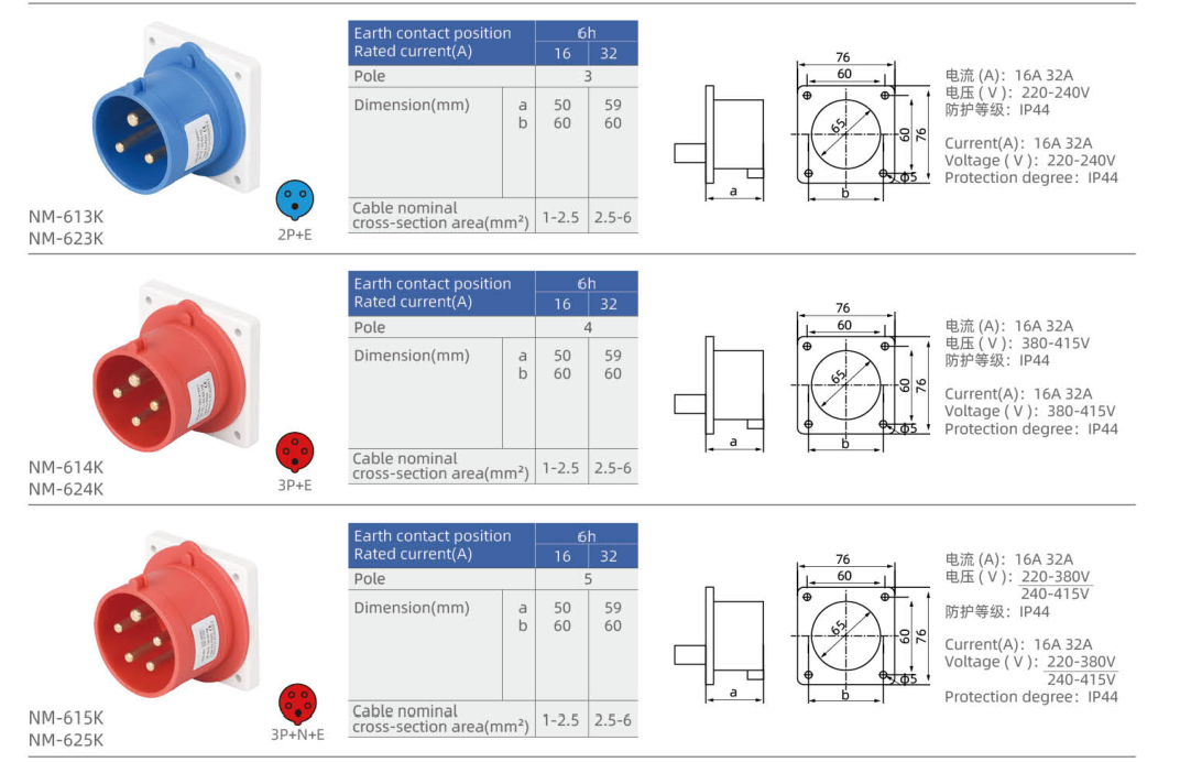
| NM-613K | Straight panel inlet, K housing | 16 | 2P+E | 220–240 V | 6h | Blue | 1–2.5 |
| NM-623K | Straight panel inlet, K housing | 32 | 2P+E | 220–240 V | 6h | Blue | 2.5–6 |
| NM-614K | Straight panel inlet, K housing | 16 | 3P+E | 380–415 V | 6h | Red | 1–2.5 |
| NM-624K | Straight panel inlet, K housing | 32 | 3P+E | 380–415 V | 6h | Red | 2.5–6 |
| NM-615K | Straight panel inlet, K housing | 16 | 3P+N+E | 220–380 V / 240–415 V | 6h | Red | 1–2.5 |
| NM-625K | Straight panel inlet, K housing | 32 | 3P+N+E | 220–380 V / 240–415 V | 6h | Red | 2.5–6 |
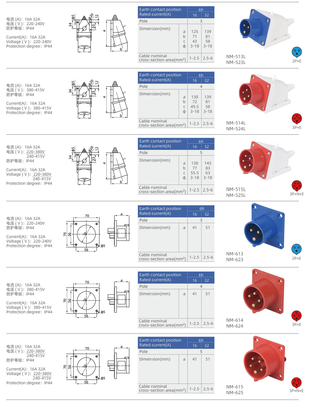
| NM-613 | Straight panel inlet | 16 | 2P+E | 220–240 V | 6h | Blue | 1–2.5 |
| NM-623 | Straight panel inlet | 32 | 2P+E | 220–240 V | 6h | Blue | 2.5–6 |
| NM-614 | Straight panel inlet | 16 | 3P+E | 380–415 V | 6h | Red | 1–2.5 |
| NM-624 | Straight panel inlet | 32 | 3P+E | 380–415 V | 6h | Red | 2.5–6 |
| NM-615 | Straight panel inlet | 16 | 3P+N+E | 220–380 V / 240–415 V | 6h | Red | 1–2.5 |
| NM-625 | Straight panel inlet | 32 | 3P+N+E | 220–380 V / 240–415 V | 6h | Red | 2.5–6 |
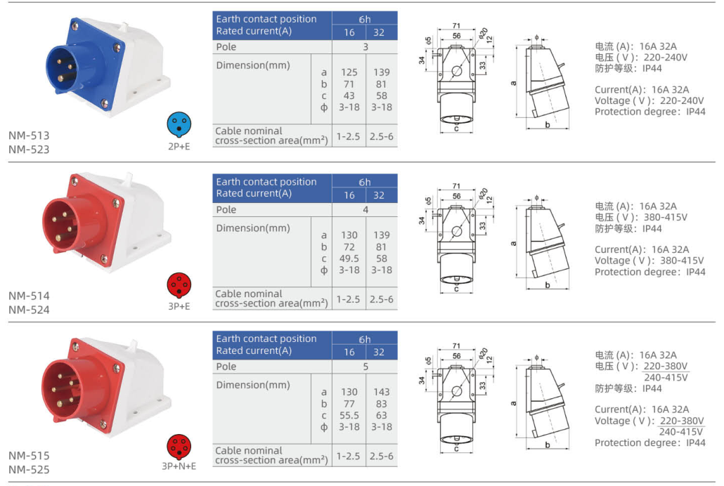
| NM-513 | Surface inlet with angled face | 16 | 2P+E | 220–240 V | 6h | Blue | 1–2.5 |
| NM-523 | Surface inlet with angled face | 32 | 2P+E | 220–240 V | 6h | Blue | 2.5–6 |
| NM-514 | Surface inlet with angled face | 16 | 3P+E | 380–415 V | 6h | Red | 1–2.5 |
| NM-524 | Surface inlet with angled face | 32 | 3P+E | 380–415 V | 6h | Red | 2.5–6 |
| NM-515 | Surface inlet with angled face | 16 | 3P+N+E | 220–380 V / 240–415 V | 6h | Red | 1–2.5 |
| NM-525 | Surface inlet with angled face | 32 | 3P+N+E | 220–380 V / 240–415 V | 6h | Red | 2.5–6 |
| NM-513L | Surface inlet with angled face — L housing | 16 | 2P+E | 220–240 V | 6h | Blue | 1–2.5 |
| NM-523L | Surface inlet with angled face — L housing | 32 | 2P+E | 220–240 V | 6h | Blue | 2.5–6 |
| NM-514L | Surface inlet with angled face — L housing | 16 | 3P+E | 380–415 V | 6h | Red | 1–2.5 |
| NM-524L | Surface inlet with angled face — L housing | 32 | 3P+E | 380–415 V | 6h | Red | 2.5–6 |
| NM-515L | Surface inlet with angled face — L housing | 16 | 3P+N+E | 220–380 V / 240–415 V | 6h | Red | 1–2.5 |
| NM-525L | Surface inlet with angled face — L housing | 32 | 3P+N+E | 220–380 V / 240–415 V | 6h | Red | 2.5–6 |
P denotes a phase contact, N neutral and E protective earth. A dash means that no voltage is assigned in this selection table.
Dimension
| Model | Lettered outline dimensions (mm) | Fixed mounting geometry |
|---|---|---|
| NM-613K | a=50, b=60 | Flange width × height (mm): 76 × 76; Fixing centres (mm): 60 × 60; Panel opening diameter (mm): 65; Fixing hole diameter (mm): 5 |
| NM-623K | a=59, b=60 | Flange width × height (mm): 76 × 76; Fixing centres (mm): 60 × 60; Panel opening diameter (mm): 65; Fixing hole diameter (mm): 5 |
| NM-614K | a=50, b=60 | Flange width × height (mm): 76 × 76; Fixing centres (mm): 60 × 60; Panel opening diameter (mm): 65; Fixing hole diameter (mm): 5 |
| NM-624K | a=59, b=60 | Flange width × height (mm): 76 × 76; Fixing centres (mm): 60 × 60; Panel opening diameter (mm): 65; Fixing hole diameter (mm): 5 |
| NM-615K | a=50, b=60 | Flange width × height (mm): 76 × 76; Fixing centres (mm): 60 × 60; Panel opening diameter (mm): 65; Fixing hole diameter (mm): 5 |
| NM-625K | a=59, b=60 | Flange width × height (mm): 76 × 76; Fixing centres (mm): 60 × 60; Panel opening diameter (mm): 65; Fixing hole diameter (mm): 5 |
| NM-613 | a=41 | Flange width × height (mm): 70 × 70; Fixing centres (mm): 56 × 56; Panel opening diameter (mm): 46; Fixing hole diameter (mm): 5 |
| NM-623 | a=51 | Flange width × height (mm): 70 × 70; Fixing centres (mm): 56 × 56; Panel opening diameter (mm): 46; Fixing hole diameter (mm): 5 |
| NM-614 | a=41 | Flange width × height (mm): 70 × 70; Fixing centres (mm): 56 × 56; Panel opening diameter (mm): 46; Fixing hole diameter (mm): 5 |
| NM-624 | a=51 | Flange width × height (mm): 70 × 70; Fixing centres (mm): 56 × 56; Panel opening diameter (mm): 46; Fixing hole diameter (mm): 5 |
| NM-615 | a=41 | Flange width × height (mm): 70 × 70; Fixing centres (mm): 56 × 56; Panel opening diameter (mm): 46; Fixing hole diameter (mm): 5 |
| NM-625 | a=51 | Flange width × height (mm): 70 × 70; Fixing centres (mm): 56 × 56; Panel opening diameter (mm): 46; Fixing hole diameter (mm): 5 |
| NM-513 | a=125, b=71, c=43, Φ=3–18 | — |
| NM-523 | a=139, b=81, c=58, Φ=3–18 | — |
| NM-514 | a=130, b=72, c=49.5, Φ=3–18 | — |
| NM-524 | a=139, b=81, c=58, Φ=3–18 | — |
| NM-515 | a=130, b=77, c=55.5, Φ=3–18 | — |
| NM-525 | a=143, b=83, c=63, Φ=3–18 | — |
| NM-513L | a=125, b=71, c=43, Φ=3–18 | — |
| NM-523L | a=139, b=81, c=58, Φ=3–18 | — |
| NM-514L | a=130, b=72, c=49.5, Φ=3–18 | — |
| NM-524L | a=139, b=81, c=58, Φ=3–18 | — |
| NM-515L | a=130, b=77, c=55.5, Φ=3–18 | — |
| NM-525L | a=143, b=83, c=63, Φ=3–18 | — |
Use the lettered dimensions with the matching inlet outline. Flange geometry and housing size differ between body versions; select the complete model code when checking installation space.
Connection Selection
Match rated current, contact configuration, voltage and earth-contact position at both sides of the connection. Select panel or surface mounting before comparing the housing dimensions. The IP rating applies to the correctly assembled connection with its compatible mating interface; maintain the specified sealing and closure arrangement.
Ordering Information
Send YOCL ELECTRIC the full model code, required quantity, supply voltage, contact configuration and installation arrangement. Include conductor cross-section and the mating cable connector when requesting a complete equipment power connection.