
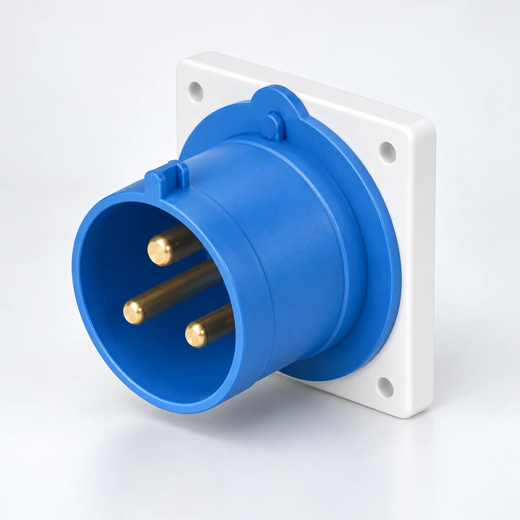
IP44 Prises industrielles pour appareils
YOCL ELECTRIC IP44 prises industrielles pour appareils en versions 16 A et 32 A. Choisissez des contacts 2P+E, 3P+E ou 3P+N+E, montage sur panneau ou en saillie et la capacité de conducteur correspondante dans le tableau des modèles.
Aperçu
Les prises industrielles pour appareils YOCL ELECTRIC IP44 fournissent une connexion d'alimentation mâle sur les machines, les équipements de distribution et les boîtiers d'équipement. La famille couvre les versions 16 A et 32 A dans des configurations 2P+E, 3P+E et 3P+N+E. Les prises droites pour montage sur panneau et les conceptions de prises en saillie encapsulées sont regroupées ici afin que l'interface d'alimentation puisse être sélectionnée avec son arrangement de montage. Un connecteur de câble femelle correspondant assure la connexion de câble détachable.
Caractéristiques
- Versions IP44 pour des connexions industrielles protégées contre les projections d'eau.
- Conceptions droites pour montage sur panneau dans des boîtiers standard et K, plus des conceptions en saillie avec une face de connecteur coudée.
- Choix 16 A et 32 A avec des plages de conducteurs indiquées pour chaque modèle.
- Position de contact de terre 6h sur les modèles listés.
- Les boîtiers de contact bleus et rouges distinguent les configurations électriques listées.
Spécifications techniques
| Paramètre | Spécification |
|---|---|
| Marque | YOCL ÉLECTRIQUE |
| Type de produit | Entrée d'appareil industrielle / Entrée mâle pour équipement |
| Indice de protection | IP44 |
| Choix de courant nominal | 16 A, 32 A |
| Configurations de contact | 2P+E ; 3P+E ; 3P+N+E |
| Position de contact de terre | h 6 |
| Montage | Montage sur panneau ou montage en saillie avec boîtier, selon le modèle |
| Interface de câble de couplage | Connecteur de câble industriel femelle correspondant |
| Capacité du conducteur | Spécifique au modèle ; voir tableau de sélection |
Sélection du modèle
| Modèle | Montage / boîtier | Courant (A) | Contacts | Tension | Position de la terre | Boîtier de contact | Conductor cross-section (mm²) |
|---|---|---|---|---|---|---|---|
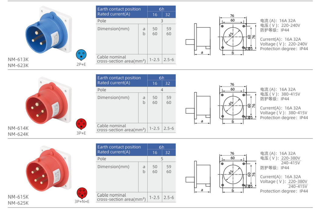
| NM-613K | Straight panel inlet, K housing | 16 | 2P+E | 220–240 V | h 6 | Bleu | 1–2.5 |
| NM-623K | Straight panel inlet, K housing | 32 | 2P+E | 220–240 V | h 6 | Bleu | 2.5–6 |
| NM-614K | Straight panel inlet, K housing | 16 | 3P+E | 380–415 V | h 6 | Rouge | 1–2.5 |
| NM-624K | Straight panel inlet, K housing | 32 | 3P+E | 380–415 V | h 6 | Rouge | 2.5–6 |
| NM-615K | Straight panel inlet, K housing | 16 | 3P+N+E | 220–380 V / 240–415 V | h 6 | Rouge | 1–2.5 |
| NM-625K | Straight panel inlet, K housing | 32 | 3P+N+E | 220–380 V / 240–415 V | h 6 | Rouge | 2.5–6 |
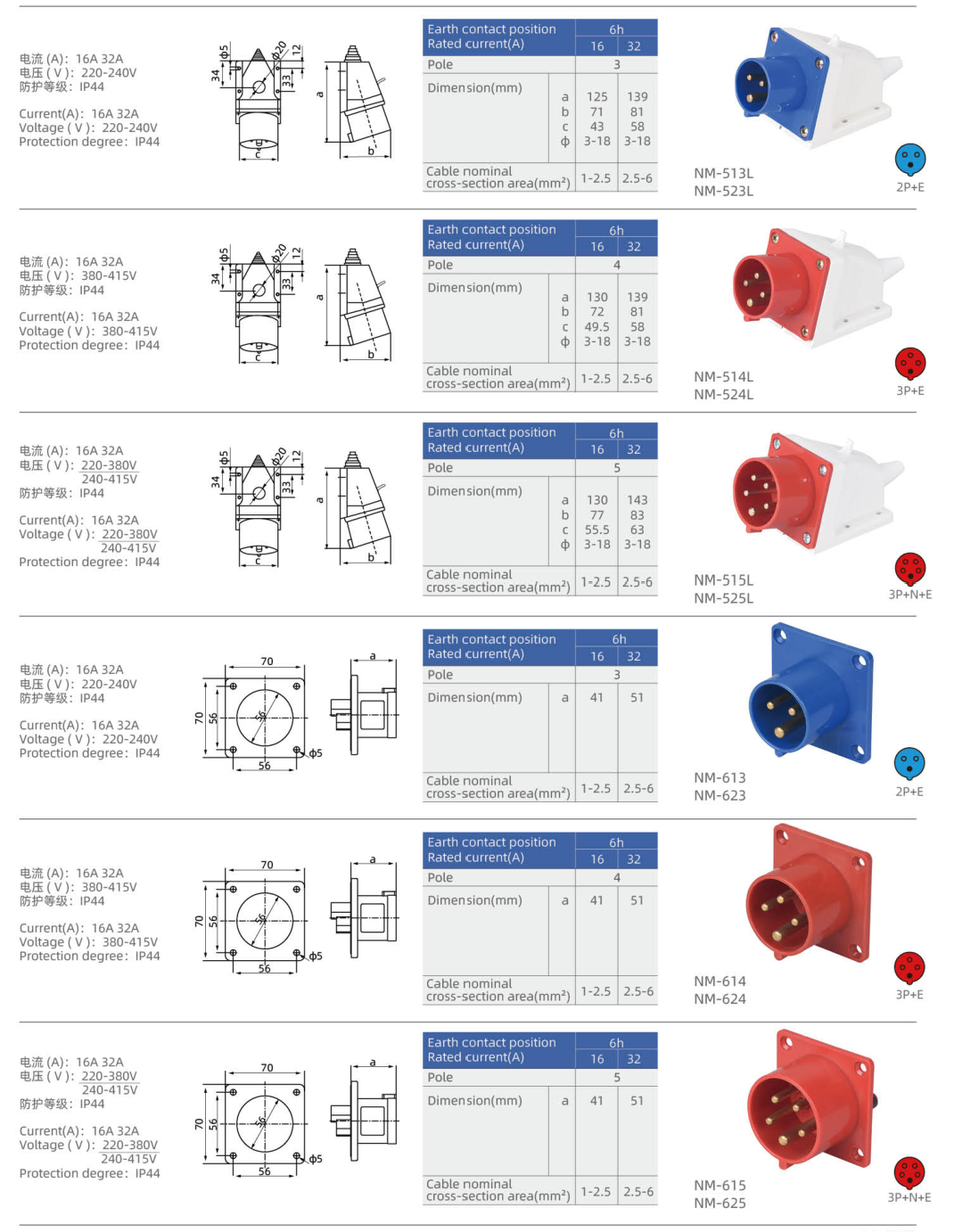
| NM-613 | Straight panel inlet | 16 | 2P+E | 220–240 V | h 6 | Bleu | 1–2.5 |
| NM-623 | Straight panel inlet | 32 | 2P+E | 220–240 V | h 6 | Bleu | 2.5–6 |
| NM-614 | Straight panel inlet | 16 | 3P+E | 380–415 V | h 6 | Rouge | 1–2.5 |
| NM-624 | Straight panel inlet | 32 | 3P+E | 380–415 V | h 6 | Rouge | 2.5–6 |
| NM-615 | Straight panel inlet | 16 | 3P+N+E | 220–380 V / 240–415 V | h 6 | Rouge | 1–2.5 |
| NM-625 | Straight panel inlet | 32 | 3P+N+E | 220–380 V / 240–415 V | h 6 | Rouge | 2.5–6 |
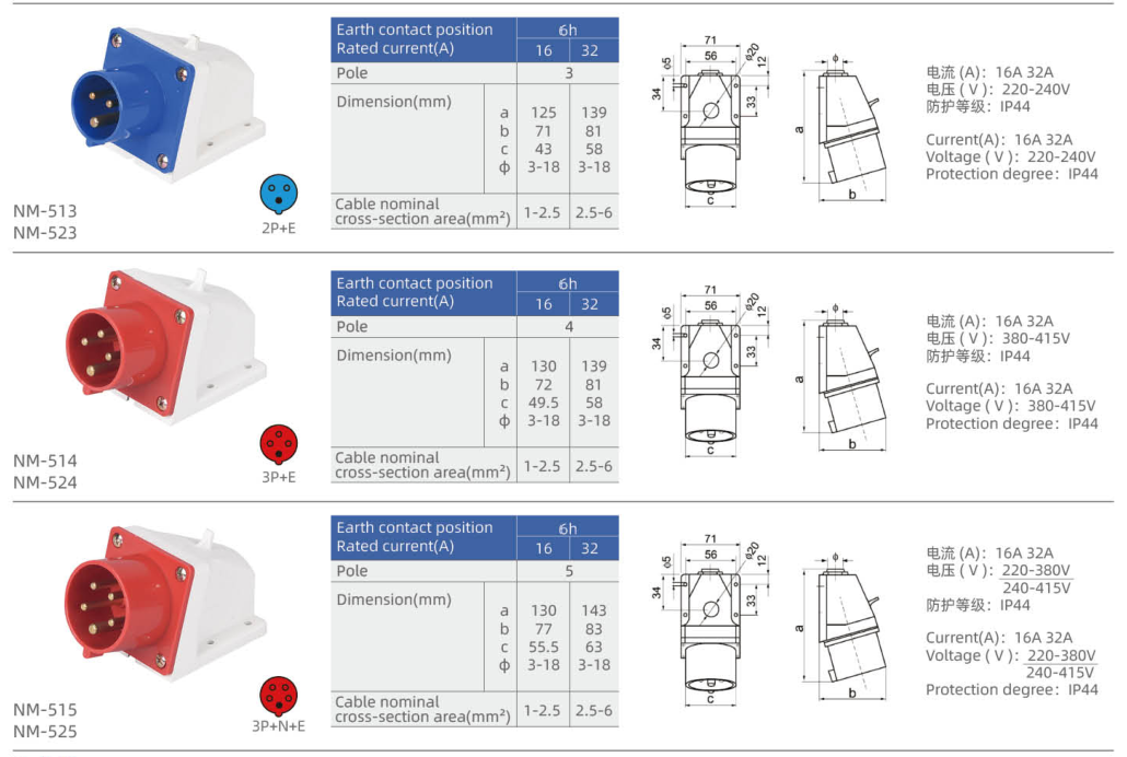
| NM-513 | Surface inlet with angled face | 16 | 2P+E | 220–240 V | h 6 | Bleu | 1–2.5 |
| NM-523 | Surface inlet with angled face | 32 | 2P+E | 220–240 V | h 6 | Bleu | 2.5–6 |
| NM-514 | Surface inlet with angled face | 16 | 3P+E | 380–415 V | h 6 | Rouge | 1–2.5 |
| NM-524 | Surface inlet with angled face | 32 | 3P+E | 380–415 V | h 6 | Rouge | 2.5–6 |
| NM-515 | Surface inlet with angled face | 16 | 3P+N+E | 220–380 V / 240–415 V | h 6 | Rouge | 1–2.5 |
| NM-525 | Surface inlet with angled face | 32 | 3P+N+E | 220–380 V / 240–415 V | h 6 | Rouge | 2.5–6 |
| NM-513L | Surface inlet with angled face — L housing | 16 | 2P+E | 220–240 V | h 6 | Bleu | 1–2.5 |
| NM-523L | Surface inlet with angled face — L housing | 32 | 2P+E | 220–240 V | h 6 | Bleu | 2.5–6 |
| NM-514L | Surface inlet with angled face — L housing | 16 | 3P+E | 380–415 V | h 6 | Rouge | 1–2.5 |
| NM-524L | Surface inlet with angled face — L housing | 32 | 3P+E | 380–415 V | h 6 | Rouge | 2.5–6 |
| NM-515L | Surface inlet with angled face — L housing | 16 | 3P+N+E | 220–380 V / 240–415 V | h 6 | Rouge | 1–2.5 |
| NM-525L | Surface inlet with angled face — L housing | 32 | 3P+N+E | 220–380 V / 240–415 V | h 6 | Rouge | 2.5–6 |
P denotes a phase contact, N neutral and E protective earth. A dash means that no voltage is assigned in this selection table.
Dimension
| Modèle | Lettered outline dimensions (mm) | Fixed mounting geometry |
|---|---|---|
| NM-613K | a=50, b=60 | Flange width × height (mm): 76 × 76; Fixing centres (mm): 60 × 60; Panel opening diameter (mm): 65; Fixing hole diameter (mm): 5 |
| NM-623K | a=59, b=60 | Flange width × height (mm): 76 × 76; Fixing centres (mm): 60 × 60; Panel opening diameter (mm): 65; Fixing hole diameter (mm): 5 |
| NM-614K | a=50, b=60 | Flange width × height (mm): 76 × 76; Fixing centres (mm): 60 × 60; Panel opening diameter (mm): 65; Fixing hole diameter (mm): 5 |
| NM-624K | a=59, b=60 | Flange width × height (mm): 76 × 76; Fixing centres (mm): 60 × 60; Panel opening diameter (mm): 65; Fixing hole diameter (mm): 5 |
| NM-615K | a=50, b=60 | Flange width × height (mm): 76 × 76; Fixing centres (mm): 60 × 60; Panel opening diameter (mm): 65; Fixing hole diameter (mm): 5 |
| NM-625K | a=59, b=60 | Flange width × height (mm): 76 × 76; Fixing centres (mm): 60 × 60; Panel opening diameter (mm): 65; Fixing hole diameter (mm): 5 |
| NM-613 | a=41 | Flange width × height (mm): 70 × 70; Fixing centres (mm): 56 × 56; Panel opening diameter (mm): 46; Fixing hole diameter (mm): 5 |
| NM-623 | a=51 | Flange width × height (mm): 70 × 70; Fixing centres (mm): 56 × 56; Panel opening diameter (mm): 46; Fixing hole diameter (mm): 5 |
| NM-614 | a=41 | Flange width × height (mm): 70 × 70; Fixing centres (mm): 56 × 56; Panel opening diameter (mm): 46; Fixing hole diameter (mm): 5 |
| NM-624 | a=51 | Flange width × height (mm): 70 × 70; Fixing centres (mm): 56 × 56; Panel opening diameter (mm): 46; Fixing hole diameter (mm): 5 |
| NM-615 | a=41 | Flange width × height (mm): 70 × 70; Fixing centres (mm): 56 × 56; Panel opening diameter (mm): 46; Fixing hole diameter (mm): 5 |
| NM-625 | a=51 | Flange width × height (mm): 70 × 70; Fixing centres (mm): 56 × 56; Panel opening diameter (mm): 46; Fixing hole diameter (mm): 5 |
| NM-513 | a=125, b=71, c=43, Φ=3–18 | — |
| NM-523 | a=139, b=81, c=58, Φ=3–18 | — |
| NM-514 | a=130, b=72, c=49.5, Φ=3–18 | — |
| NM-524 | a=139, b=81, c=58, Φ=3–18 | — |
| NM-515 | a=130, b=77, c=55.5, Φ=3–18 | — |
| NM-525 | a=143, b=83, c=63, Φ=3–18 | — |
| NM-513L | a=125, b=71, c=43, Φ=3–18 | — |
| NM-523L | a=139, b=81, c=58, Φ=3–18 | — |
| NM-514L | a=130, b=72, c=49.5, Φ=3–18 | — |
| NM-524L | a=139, b=81, c=58, Φ=3–18 | — |
| NM-515L | a=130, b=77, c=55.5, Φ=3–18 | — |
| NM-525L | a=143, b=83, c=63, Φ=3–18 | — |
Use the lettered dimensions with the matching inlet outline. Flange geometry and housing size differ between body versions; select the complete model code when checking installation space.
Sélection de connexion
Match rated current, contact configuration, voltage and earth-contact position at both sides of the connection. Select panel or surface mounting before comparing the housing dimensions. The IP rating applies to the correctly assembled connection with its compatible mating interface; maintain the specified sealing and closure arrangement.
Informations de commande
Send YOCL ELECTRIC the full model code, required quantity, supply voltage, contact configuration and installation arrangement. Include conductor cross-section and the mating cable connector when requesting a complete equipment power connection.