
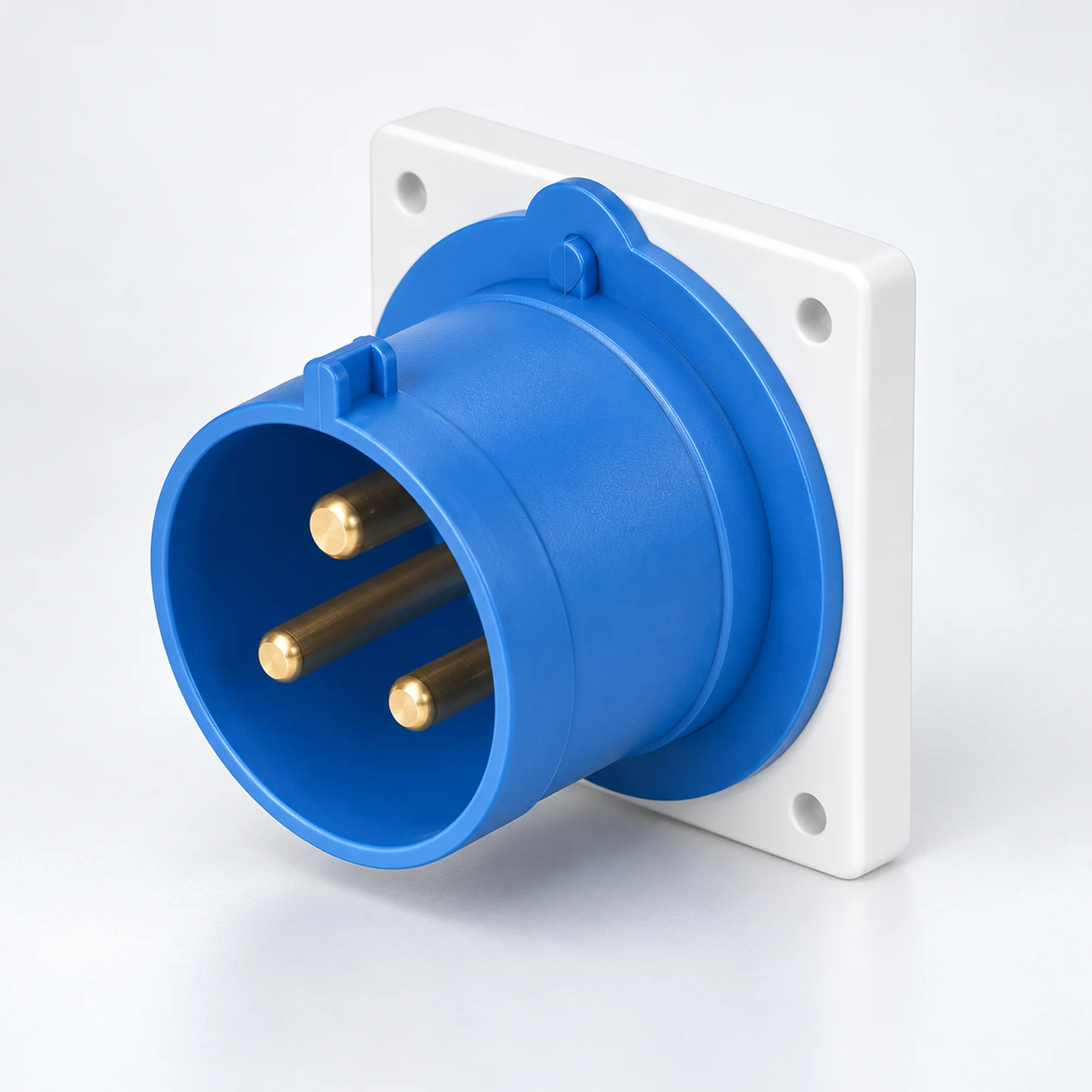
IP44 Industrielle Geräteeinlässe
YOCL ELEKTRO IP44 Industriesteckverbinder in 16 A und 32 A Ausführungen. Wählen Sie 2P+E, 3P+E oder 3P+N+E Kontakte, Frontplatten- oder Aufputzmontage und die passende Leiterkapazität aus der Modelltabelle.
Übersicht
YOCL ELEKTRO IP44 Industriesteckverbinder bieten einen männlichen Stromanschluss an Maschinen, Verteilern und Gerätegehäusen. Die Familie umfasst 16 A und 32 A Ausführungen in 2P+E, 3P+E und 3P+N+E Konfigurationen. Gerade Frontplattensteckverbinder und geschlossene Aufputz-Steckverbinderdesigns sind hier gruppiert, sodass die Versorgungsschnittstelle zusammen mit ihrer Montageart ausgewählt werden kann. Ein passender weiblicher Kabelsteckverbinder bietet den abnehmbaren Kabelanschluss.
Merkmale
- IP44 Ausführungen für spritzwassergeschützte industrielle Anschlüsse.
- Gerade Frontplatten-Designs in Standard- und K-Gehäusen sowie Aufputz-Designs mit abgewinkeltem Steckgesicht.
- 16 A und 32 A Auswahlmöglichkeiten mit Angabe der Leiterbereiche für jedes Modell.
- 6h Erdungsposition bei den aufgeführten Modellen.
- Blaue und rote Gehäusefarben unterscheiden die aufgeführten elektrischen Konfigurationen.
Technische Daten
| Parameter | Spezifikation |
|---|---|
| Marke | YOCL ELEKTRO |
| Produkttyp | Industriesteckverbinder / Gerätesteckereingang |
| Schutzart | IP44 |
| Nennstromauswahl | 16 A, 32 A |
| Kontaktbelegung | 2P+E; 3P+E; 3P+N+E |
| Erdungskontaktposition | 6h |
| Montage | Einbau- oder Aufbaugehäusemontage, je nach Modell |
| Passende Kabelverbindung | Passender Buchsen-Industriesteckverbinder |
| Leiterkapazität | Modellspezifisch; siehe Auswahltabelle |
Modellauswahl
| Modell | Montage / Gehäuse | Strom (A) | Kontakte | Spannung | Erdungsposition | Kontaktgehäuse | Conductor cross-section (mm²) |
|---|---|---|---|---|---|---|---|
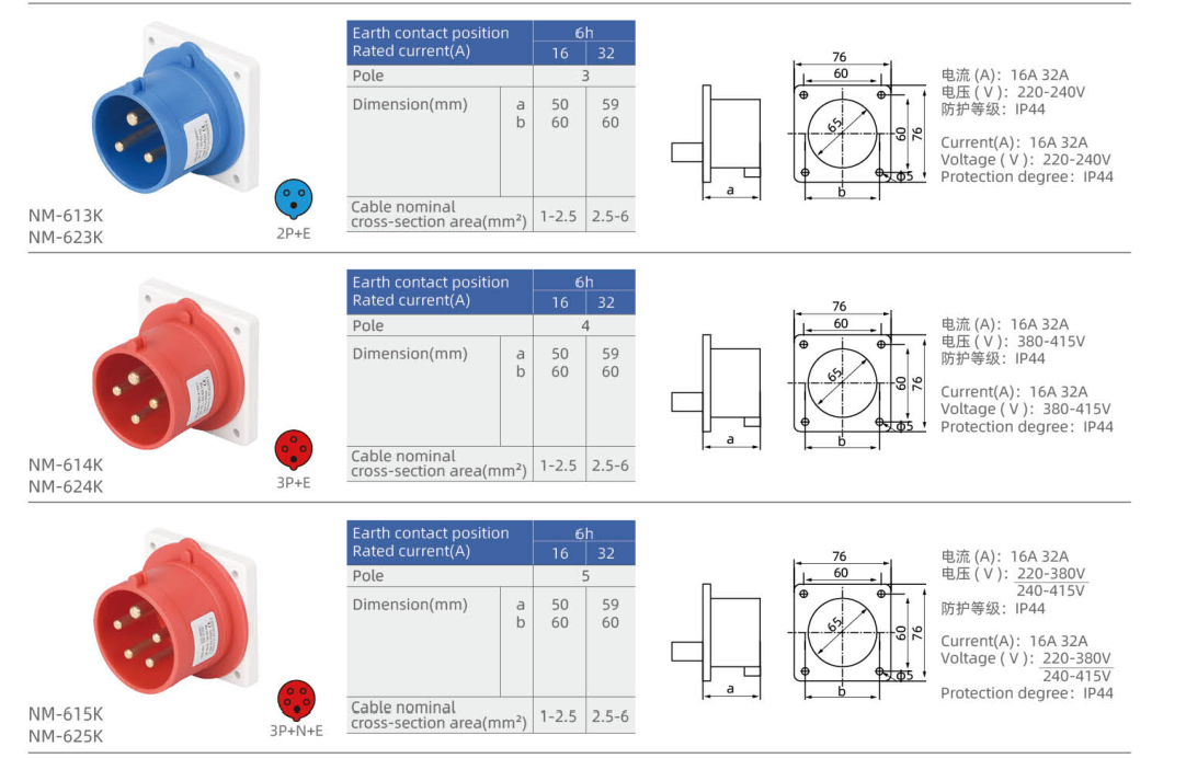
| NM-613K | Straight panel inlet, K housing | 16 | 2P+E | 220–240 V | 6h | Blau | 1–2.5 |
| NM-623K | Straight panel inlet, K housing | 32 | 2P+E | 220–240 V | 6h | Blau | 2.5–6 |
| NM-614K | Straight panel inlet, K housing | 16 | 3P+E | 380–415 V | 6h | Rot | 1–2.5 |
| NM-624K | Straight panel inlet, K housing | 32 | 3P+E | 380–415 V | 6h | Rot | 2.5–6 |
| NM-615K | Straight panel inlet, K housing | 16 | 3P+N+E | 220–380 V / 240–415 V | 6h | Rot | 1–2.5 |
| NM-625K | Straight panel inlet, K housing | 32 | 3P+N+E | 220–380 V / 240–415 V | 6h | Rot | 2.5–6 |
| NM-613 | Straight panel inlet | 16 | 2P+E | 220–240 V | 6h | Blau | 1–2.5 |
| NM-623 | Straight panel inlet | 32 | 2P+E | 220–240 V | 6h | Blau | 2.5–6 |
| NM-614 | Straight panel inlet | 16 | 3P+E | 380–415 V | 6h | Rot | 1–2.5 |
| NM-624 | Straight panel inlet | 32 | 3P+E | 380–415 V | 6h | Rot | 2.5–6 |
| NM-615 | Straight panel inlet | 16 | 3P+N+E | 220–380 V / 240–415 V | 6h | Rot | 1–2.5 |
| NM-625 | Straight panel inlet | 32 | 3P+N+E | 220–380 V / 240–415 V | 6h | Rot | 2.5–6 |
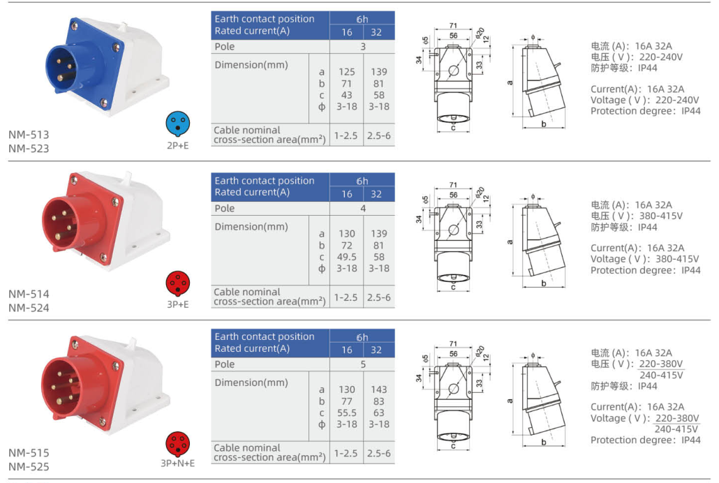
| NM-513 | Surface inlet with angled face | 16 | 2P+E | 220–240 V | 6h | Blau | 1–2.5 |
| NM-523 | Surface inlet with angled face | 32 | 2P+E | 220–240 V | 6h | Blau | 2.5–6 |
| NM-514 | Surface inlet with angled face | 16 | 3P+E | 380–415 V | 6h | Rot | 1–2.5 |
| NM-524 | Surface inlet with angled face | 32 | 3P+E | 380–415 V | 6h | Rot | 2.5–6 |
| NM-515 | Surface inlet with angled face | 16 | 3P+N+E | 220–380 V / 240–415 V | 6h | Rot | 1–2.5 |
| NM-525 | Surface inlet with angled face | 32 | 3P+N+E | 220–380 V / 240–415 V | 6h | Rot | 2.5–6 |
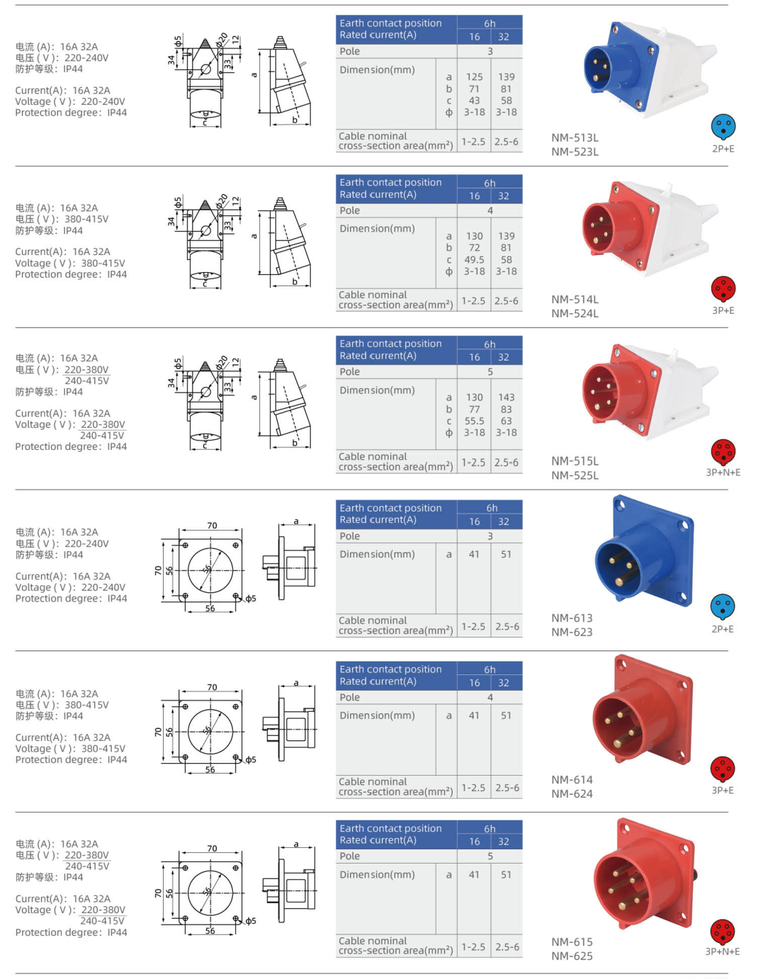
| NM-513L | Surface inlet with angled face — L housing | 16 | 2P+E | 220–240 V | 6h | Blau | 1–2.5 |
| NM-523L | Surface inlet with angled face — L housing | 32 | 2P+E | 220–240 V | 6h | Blau | 2.5–6 |
| NM-514L | Surface inlet with angled face — L housing | 16 | 3P+E | 380–415 V | 6h | Rot | 1–2.5 |
| NM-524L | Surface inlet with angled face — L housing | 32 | 3P+E | 380–415 V | 6h | Rot | 2.5–6 |
| NM-515L | Surface inlet with angled face — L housing | 16 | 3P+N+E | 220–380 V / 240–415 V | 6h | Rot | 1–2.5 |
| NM-525L | Surface inlet with angled face — L housing | 32 | 3P+N+E | 220–380 V / 240–415 V | 6h | Rot | 2.5–6 |
P denotes a phase contact, N neutral and E protective earth. A dash means that no voltage is assigned in this selection table.
Abmessung
| Modell | Lettered outline dimensions (mm) | Fixed mounting geometry |
|---|---|---|
| NM-613K | a=50, b=60 | Flange width × height (mm): 76 × 76; Fixing centres (mm): 60 × 60; Panel opening diameter (mm): 65; Fixing hole diameter (mm): 5 |
| NM-623K | a=59, b=60 | Flange width × height (mm): 76 × 76; Fixing centres (mm): 60 × 60; Panel opening diameter (mm): 65; Fixing hole diameter (mm): 5 |
| NM-614K | a=50, b=60 | Flange width × height (mm): 76 × 76; Fixing centres (mm): 60 × 60; Panel opening diameter (mm): 65; Fixing hole diameter (mm): 5 |
| NM-624K | a=59, b=60 | Flange width × height (mm): 76 × 76; Fixing centres (mm): 60 × 60; Panel opening diameter (mm): 65; Fixing hole diameter (mm): 5 |
| NM-615K | a=50, b=60 | Flange width × height (mm): 76 × 76; Fixing centres (mm): 60 × 60; Panel opening diameter (mm): 65; Fixing hole diameter (mm): 5 |
| NM-625K | a=59, b=60 | Flange width × height (mm): 76 × 76; Fixing centres (mm): 60 × 60; Panel opening diameter (mm): 65; Fixing hole diameter (mm): 5 |
| NM-613 | a=41 | Flange width × height (mm): 70 × 70; Fixing centres (mm): 56 × 56; Panel opening diameter (mm): 46; Fixing hole diameter (mm): 5 |
| NM-623 | a=51 | Flange width × height (mm): 70 × 70; Fixing centres (mm): 56 × 56; Panel opening diameter (mm): 46; Fixing hole diameter (mm): 5 |
| NM-614 | a=41 | Flange width × height (mm): 70 × 70; Fixing centres (mm): 56 × 56; Panel opening diameter (mm): 46; Fixing hole diameter (mm): 5 |
| NM-624 | a=51 | Flange width × height (mm): 70 × 70; Fixing centres (mm): 56 × 56; Panel opening diameter (mm): 46; Fixing hole diameter (mm): 5 |
| NM-615 | a=41 | Flange width × height (mm): 70 × 70; Fixing centres (mm): 56 × 56; Panel opening diameter (mm): 46; Fixing hole diameter (mm): 5 |
| NM-625 | a=51 | Flange width × height (mm): 70 × 70; Fixing centres (mm): 56 × 56; Panel opening diameter (mm): 46; Fixing hole diameter (mm): 5 |
| NM-513 | a=125, b=71, c=43, Φ=3–18 | — |
| NM-523 | a=139, b=81, c=58, Φ=3–18 | — |
| NM-514 | a=130, b=72, c=49.5, Φ=3–18 | — |
| NM-524 | a=139, b=81, c=58, Φ=3–18 | — |
| NM-515 | a=130, b=77, c=55.5, Φ=3–18 | — |
| NM-525 | a=143, b=83, c=63, Φ=3–18 | — |
| NM-513L | a=125, b=71, c=43, Φ=3–18 | — |
| NM-523L | a=139, b=81, c=58, Φ=3–18 | — |
| NM-514L | a=130, b=72, c=49.5, Φ=3–18 | — |
| NM-524L | a=139, b=81, c=58, Φ=3–18 | — |
| NM-515L | a=130, b=77, c=55.5, Φ=3–18 | — |
| NM-525L | a=143, b=83, c=63, Φ=3–18 | — |
Use the lettered dimensions with the matching inlet outline. Flange geometry and housing size differ between body versions; select the complete model code when checking installation space.
Anschlusswahl
Match rated current, contact configuration, voltage and earth-contact position at both sides of the connection. Select panel or surface mounting before comparing the housing dimensions. The IP rating applies to the correctly assembled connection with its compatible mating interface; maintain the specified sealing and closure arrangement.
Bestellinformationen
Send YOCL ELECTRIC the full model code, required quantity, supply voltage, contact configuration and installation arrangement. Include conductor cross-section and the mating cable connector when requesting a complete equipment power connection.