
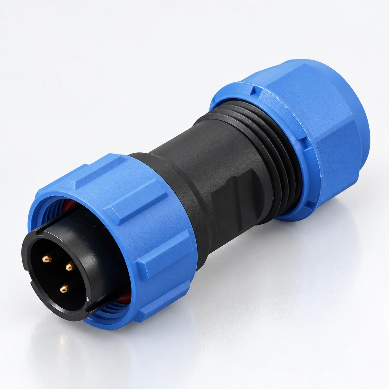
SP17 Konektor Bundar Tahan Air
YOCL ELECTRIC SP17 konektor melingkar tahan air menyediakan sambungan kabel dan panel berulir dengan tujuh susunan kontak.
- kontak 2, 3, 4, 5, 7, 9, atau 10
- tingkat perlindungan IP68; rentang suhu −40 °C hingga +85 °C
- Peringkat solder: 10 A untuk kontak 2/3, 5 A untuk kontak 4/5/7/9/10
- Tegangan kerja: 500 V AC untuk kontak 2–5; 400 V AC untuk kontak 7/9/10, untuk konfigurasi solder
- Steker lurus dan sudut siku dengan format soket inline dan panel
Tinjauan
YOCL LISTRIK SP17 konektor melingkar tahan air menggunakan kopling berulir untuk menghubungkan kabel ke soket kabel atau panel yang cocok. Seri ini mencakup colokan kabel lurus dan sudut siku, soket kabel inline, dan empat format soket panel.
SP17 menawarkan kontak 2, 3, 4, 5, 7, 9, atau 10. Konfigurasi kontak solder diberi peringkat 10 A untuk kontak 2 dan 3, atau 5 A untuk kontak 4, 5, 7, 9, dan 10. Tegangan kerja juga bervariasi dengan jumlah kontak. Pilih susunan kontak, terminasi, dan format pemasangan bersama-sama menggunakan tabel di bawah ini.
Fitur
- Kopling berulir mempertahankan colokan dan soket yang cocok.
- Tujuh susunan kontak mencakup kontak 2, 3, 4, 5, 7, 9, dan 10.
- IP68 tingkat perlindungan dengan komponen penyegelan kabel dan penutup konektor yang ditampilkan untuk seri ini.
- Kontak tembaga berlapis emas dan isolator PPS.
- Steker lurus dan sudut siku mendukung arah keluar kabel yang berbeda.
- Format soket kabel dan panel memungkinkan koneksi inline atau pemasangan peralatan.
Spesifikasi Teknis
Data Seri
| Parameter | Spesifikasi |
|---|---|
| Merek | YOCL ELEKTRIK |
| Seri | SP17 |
| Kopling | Penguncian ulir |
| Jumlah kontak | 2, 3, 4, 5, 7, 9, 10 |
| Bahan kontak | Tembaga berlapis emas |
| Bahan housing | Termoplastik PC / PA66 |
| Rating nyala rumah | V-0 |
| Isolator | PPS termoplastik |
| Tingkat perlindungan | IP68 |
| Rentang suhu | −40 °C hingga +85 °C |
| Siklus penyambungan | 500 |
| Resistansi isolasi | 2000 MΩ |
| Opsi terminasi | Solder dan crimp, tergantung pada konektor yang dipilih |
| Steker kabel lurus / soket kabel inline diameter luar kabel | 6–10 mm |
Penunjukan IP68 tidak menentukan kedalaman atau durasi perendaman dalam data yang diberikan. Cocokkan segel kabel dengan konektor yang dipilih dan diameter luar kabel.
Rating Kontak Solder
Data listrik dan konduktor berikut berlaku untuk konfigurasi kontak solder. Mereka bukan tabel peringkat terpisah untuk konfigurasi pengakhiran crimp atau lainnya.
| Kontak | Arus terukur | Diameter kontak × kuantitas | Tegangan kerja | tegangan tahan AC, 1 menit | Resistansi kontak | Bagian konduktor maksimum | Nilai AWG berpasangan |
|---|---|---|---|---|---|---|---|
| 2 | 10 A | Ø1.5 mm × 2 | 500 V AC | 1500 V AC | 2.5 mΩ | ≤ 2 mm² | 14 AWG |
| 3 | 10 A | Ø1.5 mm × 3 | 500 V AC | 1500 V AC | 2.5 mΩ | ≤ 2 mm² | 14 AWG |
| 4 | 5 A | Ø1.0 mm × 4 | 500 V AC | 1500 V AC | 5 mΩ | ≤ 0.75 mm² | 18 AWG |
| 5 | 5 A | Ø1.0 mm × 5 | 500 V AC | 1500 V AC | 5 mΩ | ≤ 0.75 mm² | 18 AWG |
| 7 | 5 A | Ø1.0 mm × 7 | 400 V AC | 1200 V AC | 5 mΩ | ≤ 0.75 mm² | 18 AWG |
| 9 | 5 A | Ø1.0 mm × 9 | 400 V AC | 1200 V AC | 5 mΩ | ≤ 0.75 mm² | 18 AWG |
| 10 | 5 A | Ø1.0 mm × 10 | 400 V AC | 1200 V AC | 5 mΩ | ≤ 0.75 mm² | 18 AWG |
The conductor limits and paired AWG values are retained as listed. AWG values are not an additional independently converted size range. The 1-minute withstand voltage is a test parameter, separate from the working voltage.
Dimensi
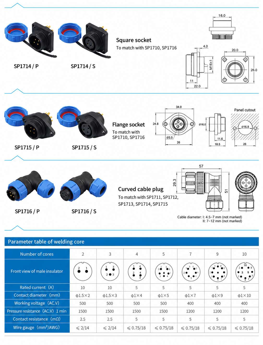
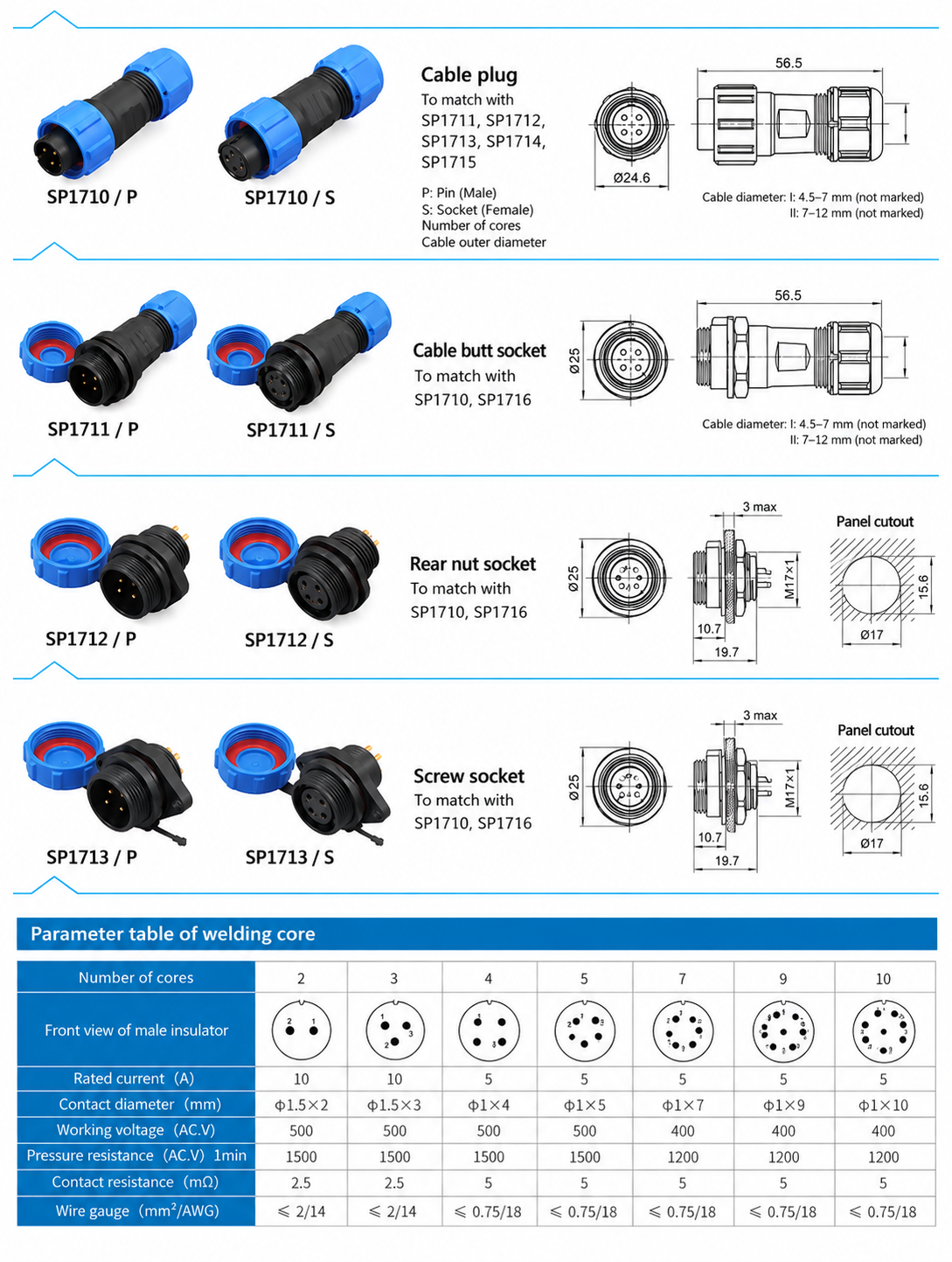
Dimensions below are in milimeter. Body dimensions and panel openings describe different features and should be checked for the chosen format.
Dimensi Badan Konektor
| Format | Model dasar | Dimensi badan yang tercantum |
|---|---|---|
| Straight cable plug | SP1710 | Length 56.5; front diameter Ø24.6 |
| Inline cable receptacle | SP1711 | Length 56.5; front diameter Ø25 |
| Rear-nut panel receptacle | SP1712 | Length 19.7; front projection 10.7; front diameter Ø25; mounting thread M17 × 1 |
| Screw socket format | SP1713 | Length 19.7; front projection 10.7; front diameter Ø25; mounting thread M17 × 1 |
| Square panel receptacle | SP1714 | Length 22.0; front projection 11; flange thickness 4.0; flange vertical size 26.0; rear thread M16 × 1 |
| Flange panel receptacle | SP1715 | Flange width 34.0; height 24.8; body spigot diameter Ø16.0 |
| Right-angle cable plug | SP1716 | Overall horizontal extent 57; vertical extent 51; front vertical extent 29.3 |
Panel Opening Data
| Panel format | Listed opening data |
|---|---|
| SP1712 / SP1713 | Keyed opening Ø17 with 15.6 across flats; maximum panel thickness 3 |
| SP1715 | Central opening Ø16.8; fixing holes Ø3.5 |
Check the complete mounting drawing before machining a panel, including fixing-hole positions and the required clearance around the connector.
Format Konektor dan Pemilihan Pasangan
Each base model is shown in /P dan /S contact versions. P identifies male pin contacts; S identifies female socket contacts. Contact gender is separate from whether the connector body is a cable plug or a receptacle.
| Model dasar | Format | Matching base models |
|---|---|---|
| SP1710 | Straight cable plug | SP1711, SP1712, SP1713, SP1714, SP1715 |
| SP1711 | Inline cable receptacle | SP1710, SP1716 |
| SP1712 | Rear-nut panel receptacle | SP1710, SP1716 |
| SP1713 | Screw socket format | SP1710, SP1716 |
| SP1714 | Square panel receptacle | SP1710, SP1716 |
| SP1715 | Flange panel receptacle | SP1710, SP1716 |
| SP1716 | Right-angle cable plug | SP1711, SP1712, SP1713, SP1714, SP1715 |
Choose a compatible pin/socket pair with the same contact count and arrangement. The table identifies mating body families, rather than a complete orderable part number.
Panduan Identifikasi dan Pemilihan Model
Misalnya, SP1710/P identifies the straight cable plug with pin contacts, while SP1711/S identifies the inline cable receptacle with socket contacts. Contact count and termination still need to be specified.
The SP1710 code legend identifies solder termination as code 1, normally unmarked, and crimp termination as code 3. State the required termination in an enquiry; do not select a crimp configuration solely from the solder rating table.
- Select the contact count and check its solder working voltage and rated current where applicable.
- Choose a straight or right-angle cable plug and a matching cable or panel receptacle.
- Specify P pin contacts or S socket contacts for each mating half.
- State the conductor size and termination method.
- State the cable outer diameter for each cable connector and the panel mounting format for each panel receptacle.
Informasi Pemesanan
For an SP17 enquiry, provide the base model, contact count, P/S contact version, termination, conductor size, cable outer diameter and quantity. For panel receptacles, include the mounting format and available panel thickness. For right-angle plugs, include the cable exit direction and cable diameter so the corresponding seal configuration can be selected.