
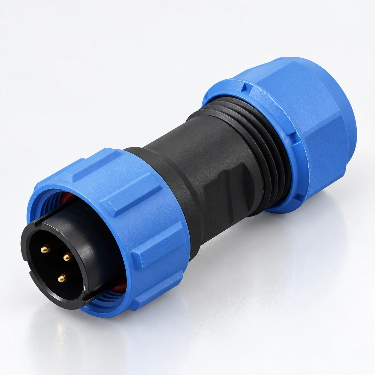
SP17 Waterproof Circular Connectors
YOCL ELECTRIC SP17 waterproof circular connectors provide threaded cable and panel connections with seven contact arrangements.
- 2, 3, 4, 5, 7, 9 or 10 contacts
- IP68 protection grade; −40 °C to +85 °C temperature range
- Solder ratings: 10 A for 2/3 contacts, 5 A for 4/5/7/9/10 contacts
- Working voltage: 500 V AC for 2–5 contacts; 400 V AC for 7/9/10 contacts, for solder configurations
- Straight and right-angle plugs with inline and panel receptacle formats
Overview
YOCL ELECTRIC SP17 waterproof circular connectors use a threaded coupling to connect cables to matching cable or panel receptacles. The series includes straight and right-angle cable plugs, an inline cable receptacle and four panel receptacle formats.
SP17 offers 2, 3, 4, 5, 7, 9 or 10 contacts. Solder contact configurations are rated at 10 A for 2 and 3 contacts, or 5 A for 4, 5, 7, 9 and 10 contacts. Working voltage also varies with contact count. Select the contact arrangement, termination and mating format together using the tables below.
Features
- Threaded coupling retains the matching plug and receptacle.
- Seven contact arrangements cover 2, 3, 4, 5, 7, 9 and 10 contacts.
- IP68 protection grade with cable sealing components and connector covers shown for the series.
- Gold-plated copper contacts and a PPS insulator.
- Straight and right-angle plugs support different cable exit directions.
- Cable and panel receptacle formats allow inline connections or equipment mounting.
Technical Specifications
Series Data
| Parameter | Specification |
|---|---|
| Brand | YOCL ELECTRIC |
| Series | SP17 |
| Coupling | Thread locking |
| Contact counts | 2, 3, 4, 5, 7, 9, 10 |
| Contact material | Gold-plated copper |
| Housing material | Thermoplastic PC / PA66 |
| Housing flame rating | V-0 |
| Insulator | Thermoplastic PPS |
| Protection grade | IP68 |
| Temperature range | −40 °C to +85 °C |
| Mating cycles | 500 |
| Insulation resistance | 2000 MΩ |
| Termination options | Solder and crimp, depending on the selected connector |
| Straight cable plug / inline cable receptacle cable OD | 6–10 mm |
The IP68 designation does not specify an immersion depth or duration in the supplied data. Match the cable seal to the selected connector and cable outer diameter.
Solder Contact Ratings
The following electrical and conductor data apply to the solder contact configurations. They are not a separate rating table for crimp or other termination configurations.
| Contacts | Rated current | Contact diameter × quantity | Working voltage | AC withstand voltage, 1 minute | Contact resistance | Maximum conductor section | Paired AWG value |
|---|---|---|---|---|---|---|---|
| 2 | 10 A | Ø1.5 mm × 2 | 500 V AC | 1500 V AC | 2.5 mΩ | ≤ 2 mm² | 14 AWG |
| 3 | 10 A | Ø1.5 mm × 3 | 500 V AC | 1500 V AC | 2.5 mΩ | ≤ 2 mm² | 14 AWG |
| 4 | 5 A | Ø1.0 mm × 4 | 500 V AC | 1500 V AC | 5 mΩ | ≤ 0.75 mm² | 18 AWG |
| 5 | 5 A | Ø1.0 mm × 5 | 500 V AC | 1500 V AC | 5 mΩ | ≤ 0.75 mm² | 18 AWG |
| 7 | 5 A | Ø1.0 mm × 7 | 400 V AC | 1200 V AC | 5 mΩ | ≤ 0.75 mm² | 18 AWG |
| 9 | 5 A | Ø1.0 mm × 9 | 400 V AC | 1200 V AC | 5 mΩ | ≤ 0.75 mm² | 18 AWG |
| 10 | 5 A | Ø1.0 mm × 10 | 400 V AC | 1200 V AC | 5 mΩ | ≤ 0.75 mm² | 18 AWG |
The conductor limits and paired AWG values are retained as listed. AWG values are not an additional independently converted size range. The 1-minute withstand voltage is a test parameter, separate from the working voltage.
Dimension
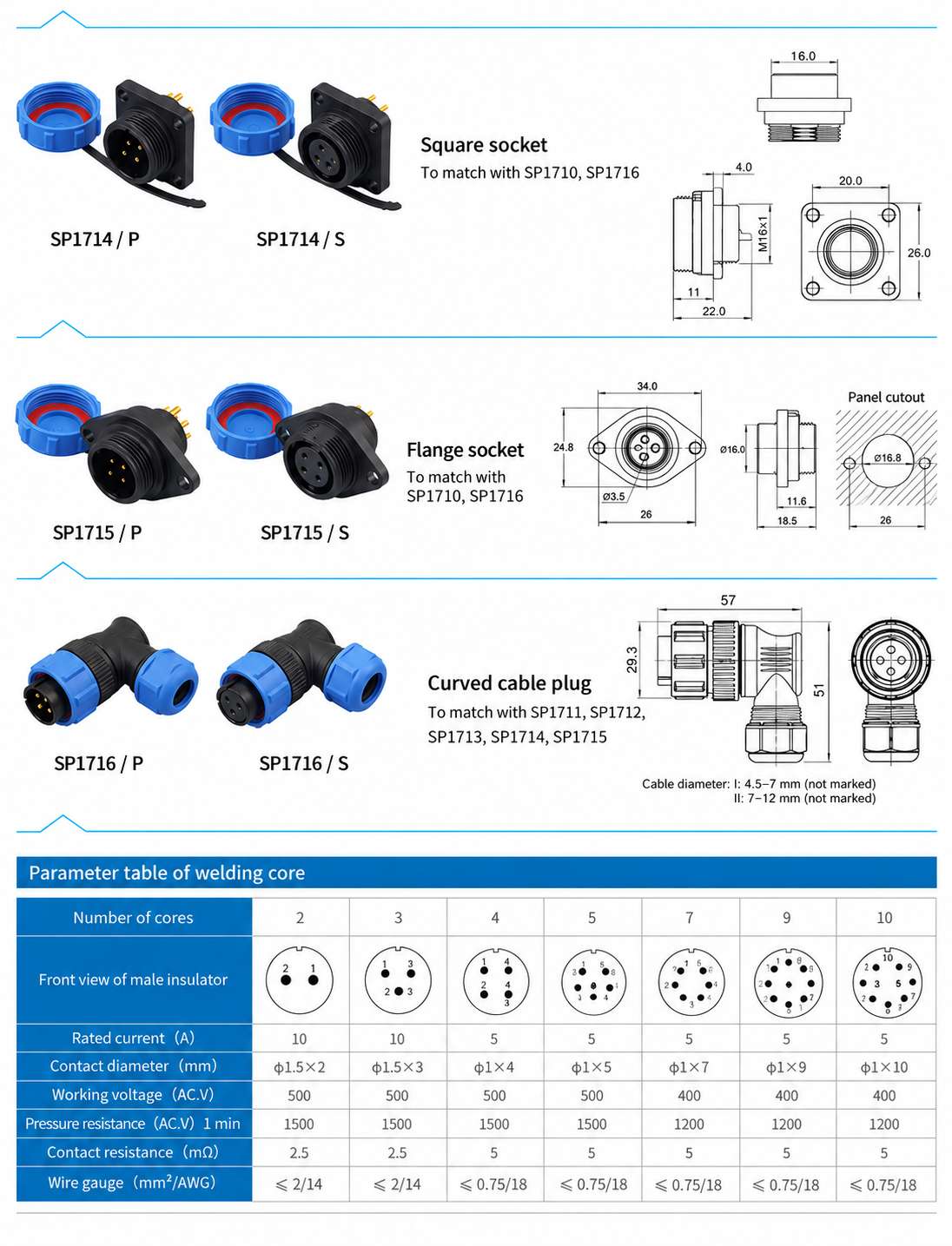
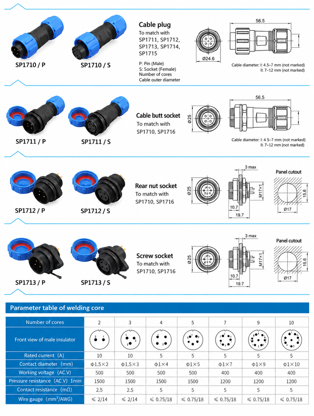
Dimensions below are in millimetres. Body dimensions and panel openings describe different features and should be checked for the chosen format.
Connector Body Dimensions
| Format | Base model | Listed body dimensions |
|---|---|---|
| Straight cable plug | SP1710 | Length 56.5; front diameter Ø24.6 |
| Inline cable receptacle | SP1711 | Length 56.5; front diameter Ø25 |
| Rear-nut panel receptacle | SP1712 | Length 19.7; front projection 10.7; front diameter Ø25; mounting thread M17 × 1 |
| Screw socket format | SP1713 | Length 19.7; front projection 10.7; front diameter Ø25; mounting thread M17 × 1 |
| Square panel receptacle | SP1714 | Length 22.0; front projection 11; flange thickness 4.0; flange vertical size 26.0; rear thread M16 × 1 |
| Flange panel receptacle | SP1715 | Flange width 34.0; height 24.8; body spigot diameter Ø16.0 |
| Right-angle cable plug | SP1716 | Overall horizontal extent 57; vertical extent 51; front vertical extent 29.3 |
Panel Opening Data
| Panel format | Listed opening data |
|---|---|
| SP1712 / SP1713 | Keyed opening Ø17 with 15.6 across flats; maximum panel thickness 3 |
| SP1715 | Central opening Ø16.8; fixing holes Ø3.5 |
Check the complete mounting drawing before machining a panel, including fixing-hole positions and the required clearance around the connector.
Connector Formats and Mating Selection
Each base model is shown in /P and /S contact versions. P identifies male pin contacts; S identifies female socket contacts. Contact gender is separate from whether the connector body is a cable plug or a receptacle.
| Base model | Format | Matching base models |
|---|---|---|
| SP1710 | Straight cable plug | SP1711, SP1712, SP1713, SP1714, SP1715 |
| SP1711 | Inline cable receptacle | SP1710, SP1716 |
| SP1712 | Rear-nut panel receptacle | SP1710, SP1716 |
| SP1713 | Screw socket format | SP1710, SP1716 |
| SP1714 | Square panel receptacle | SP1710, SP1716 |
| SP1715 | Flange panel receptacle | SP1710, SP1716 |
| SP1716 | Right-angle cable plug | SP1711, SP1712, SP1713, SP1714, SP1715 |
Choose a compatible pin/socket pair with the same contact count and arrangement. The table identifies mating body families, rather than a complete orderable part number.
Model Identification and Selection Guide
For example, SP1710/P identifies the straight cable plug with pin contacts, while SP1711/S identifies the inline cable receptacle with socket contacts. Contact count and termination still need to be specified.
The SP1710 code legend identifies solder termination as code 1, normally unmarked, and crimp termination as code 3. State the required termination in an enquiry; do not select a crimp configuration solely from the solder rating table.
- Select the contact count and check its solder working voltage and rated current where applicable.
- Choose a straight or right-angle cable plug and a matching cable or panel receptacle.
- Specify P pin contacts or S socket contacts for each mating half.
- State the conductor size and termination method.
- State the cable outer diameter for each cable connector and the panel mounting format for each panel receptacle.
Ordering Information
For an SP17 enquiry, provide the base model, contact count, P/S contact version, termination, conductor size, cable outer diameter and quantity. For panel receptacles, include the mounting format and available panel thickness. For right-angle plugs, include the cable exit direction and cable diameter so the corresponding seal configuration can be selected.