
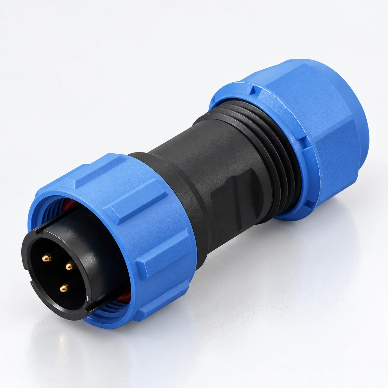
SP17 Su Geçirmez Yuvarlak Konnektörler
YOCL ELEKTRIK SP17 su geçirmez dairesel konektörler, yedi kontak düzeniyle dişli kablo ve panel bağlantıları sağlar.
- 2, 3, 4, 5, 7, 9 veya 10 kontaklar
- IP68 koruma sınıfı; −40 °C ila +85 °C sıcaklık aralığı
- Lehim dereceleri: 10 A 2/3 kontaklar için, 5 A 4/5/7/9/10 kontaklar için
- Çalışma voltajı: 500 V AC 2–5 kontaklar için; 400 V AC 7/9/10 kontaklar için, lehim konfigürasyonları için
- Düz ve dik açılı fişler, hat içi ve panel priz formatlarında
Genel Bakış
YOCL ELEKTRİKLİ SP17 su geçirmez dairesel konektörler kabloları eşleşen kablo veya panel prizlerine bağlamak için dişli bir kuplaj kullanır. Seri, düz ve dik açılı kablo fişleri, hat içi bir kablo prizi ve dört panel priz formatı içerir.
SP17 sunar 2, 3, 4, 5, 7, 9 veya 10 kontaklar. Lehimli kontak konfigürasyonları, 2 ve 3 kontaklar için 10 A veya 4, 5, 7, 9 ve 10 kontaklar için 5 A olarak derecelendirilmiştir. Çalışma voltajı da kontak sayısına göre değişir. Aşağıdaki tablolarda kontak düzenini, sonlandırmayı ve eşleşme formatını birlikte seçin.
Özellikler
- Dişli kuplaj eşleşen fişi ve prizi tutar.
- Yedi kontak düzeni 2, 3, 4, 5, 7, 9 ve 10 kontakları kapsar.
- IP68 koruma sınıfı seri için kablo contalama bileşenleri ve konektör kapakları gösterilmiştir.
- Altın kaplama bakır kontaklar ve bir PPS yalıtkanı.
- Düz ve dik açılı fişler farklı kablo çıkış yönlerini destekler.
- Kablo ve panel soket formatları sıralı bağlantılara veya ekipman montajına izin verir.
Teknik Özellikler
Seri Verileri
| Parametre | Teknik Özellikler |
|---|---|
| Marka | YOCL ELEKTRİK |
| Seri | SP17 |
| Kavrama | Diş kilitleme |
| Kontak sayısı | 2, 3, 4, 5, 7, 9, 10 |
| Kontak malzemesi | Altın kaplama bakır |
| Gövde malzemesi | Termoplastik PC / PA66 |
| Gövde alev derecesi | V-0 |
| Yalıtkan | Termoplastik PPS |
| Koruma sınıfı | IP68 |
| Sıcaklık aralığı | −40 °C ila +85 °C |
| Eşleşme döngüleri | 500 |
| Yalıtım direnci | 2000 MΩ |
| Sonlandırma seçenekleri | Seçilen konektöre bağlı olarak lehim ve sıkma |
| Düz kablo fişi / hat kablo soketi kablo OD | 6–10 mm |
IP68 tanımı, sağlanan verilerde bir daldırma derinliği veya süresi belirtmez. Kablo contasını seçilen konektör ve kablo dış çapına göre eşleştirin.
Lehimli Kontak Derecelendirmeleri
Aşağıdaki elektriksel ve iletken verileri şunlar için geçerlidir: lehim temas konfigürasyonları. Sıkma veya diğer sonlandırma konfigürasyonları için ayrı bir derecelendirme tablosu değildir.
| Kontaklar | Anma akımı | Kontak çapı × miktar | Çalışma gerilimi | AC dayanım gerilimi, 1 dakika | Kontak direnci | Maksimum iletken kesiti | Eşleştirilmiş AWG değeri |
|---|---|---|---|---|---|---|---|
| 2 | 10 A | Ø1.5 mm × 2 | 500 V AC | 1500 V AC | 2.5 mΩ | ≤ 2 mm² | 14 AWG |
| 3 | 10 A | Ø1.5 mm × 3 | 500 V AC | 1500 V AC | 2.5 mΩ | ≤ 2 mm² | 14 AWG |
| 4 | 5 A | Ø1.0 mm × 4 | 500 V AC | 1500 V AC | 5 mΩ | ≤ 0.75 mm² | 18 AWG |
| 5 | 5 A | Ø1.0 mm × 5 | 500 V AC | 1500 V AC | 5 mΩ | ≤ 0.75 mm² | 18 AWG |
| 7 | 5 A | Ø1.0 mm × 7 | 400 V AC | 1200 V AC | 5 mΩ | ≤ 0.75 mm² | 18 AWG |
| 9 | 5 A | Ø1.0 mm × 9 | 400 V AC | 1200 V AC | 5 mΩ | ≤ 0.75 mm² | 18 AWG |
| 10 | 5 A | Ø1.0 mm × 10 | 400 V AC | 1200 V AC | 5 mΩ | ≤ 0.75 mm² | 18 AWG |
The conductor limits and paired AWG values are retained as listed. AWG values are not an additional independently converted size range. The 1-minute withstand voltage is a test parameter, separate from the working voltage.
Boyut
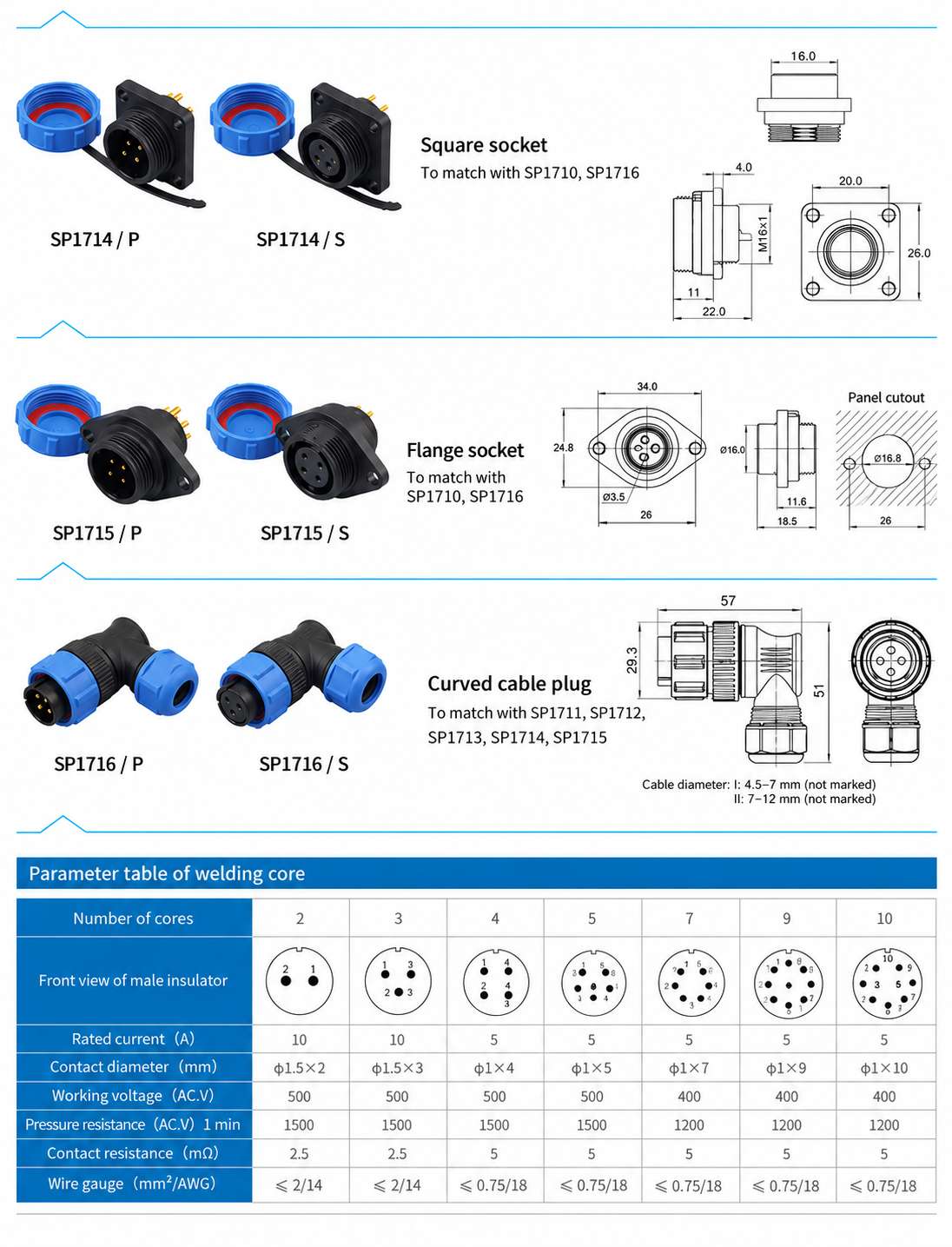
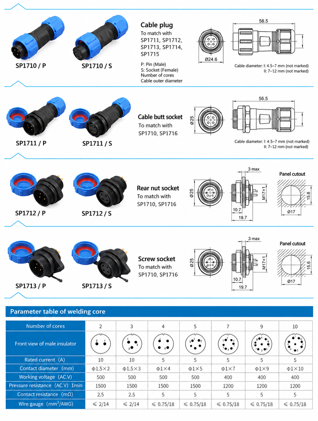
Dimensions below are in milimetre. Body dimensions and panel openings describe different features and should be checked for the chosen format.
Konnektör Gövde Boyutları
| Format | Temel model | Listelenen gövde boyutları |
|---|---|---|
| Straight cable plug | SP1710 | Length 56.5; front diameter Ø24.6 |
| Inline cable receptacle | SP1711 | Length 56.5; front diameter Ø25 |
| Rear-nut panel receptacle | SP1712 | Length 19.7; front projection 10.7; front diameter Ø25; mounting thread M17 × 1 |
| Screw socket format | SP1713 | Length 19.7; front projection 10.7; front diameter Ø25; mounting thread M17 × 1 |
| Square panel receptacle | SP1714 | Length 22.0; front projection 11; flange thickness 4.0; flange vertical size 26.0; rear thread M16 × 1 |
| Flange panel receptacle | SP1715 | Flange width 34.0; height 24.8; body spigot diameter Ø16.0 |
| Right-angle cable plug | SP1716 | Overall horizontal extent 57; vertical extent 51; front vertical extent 29.3 |
Panel Opening Data
| Panel format | Listed opening data |
|---|---|
| SP1712 / SP1713 | Keyed opening Ø17 with 15.6 across flats; maximum panel thickness 3 |
| SP1715 | Central opening Ø16.8; fixing holes Ø3.5 |
Check the complete mounting drawing before machining a panel, including fixing-hole positions and the required clearance around the connector.
Konektör Formatları ve Eşleştirme Seçimi
Each base model is shown in /P ve /S contact versions. P identifies male pin contacts; S identifies female socket contacts. Contact gender is separate from whether the connector body is a cable plug or a receptacle.
| Temel model | Format | Matching base models |
|---|---|---|
| SP1710 | Straight cable plug | SP1711, SP1712, SP1713, SP1714, SP1715 |
| SP1711 | Inline cable receptacle | SP1710, SP1716 |
| SP1712 | Rear-nut panel receptacle | SP1710, SP1716 |
| SP1713 | Screw socket format | SP1710, SP1716 |
| SP1714 | Square panel receptacle | SP1710, SP1716 |
| SP1715 | Flange panel receptacle | SP1710, SP1716 |
| SP1716 | Right-angle cable plug | SP1711, SP1712, SP1713, SP1714, SP1715 |
Choose a compatible pin/socket pair with the same contact count and arrangement. The table identifies mating body families, rather than a complete orderable part number.
Model Tanımlama ve Seçim Kılavuzu
Örneğin, SP1710/P identifies the straight cable plug with pin contacts, while SP1711/S identifies the inline cable receptacle with socket contacts. Contact count and termination still need to be specified.
The SP1710 code legend identifies solder termination as code 1, normally unmarked, and crimp termination as code 3. State the required termination in an enquiry; do not select a crimp configuration solely from the solder rating table.
- Select the contact count and check its solder working voltage and rated current where applicable.
- Choose a straight or right-angle cable plug and a matching cable or panel receptacle.
- Specify P pin contacts or S socket contacts for each mating half.
- State the conductor size and termination method.
- State the cable outer diameter for each cable connector and the panel mounting format for each panel receptacle.
Sipariş Bilgileri
For an SP17 enquiry, provide the base model, contact count, P/S contact version, termination, conductor size, cable outer diameter and quantity. For panel receptacles, include the mounting format and available panel thickness. For right-angle plugs, include the cable exit direction and cable diameter so the corresponding seal configuration can be selected.