
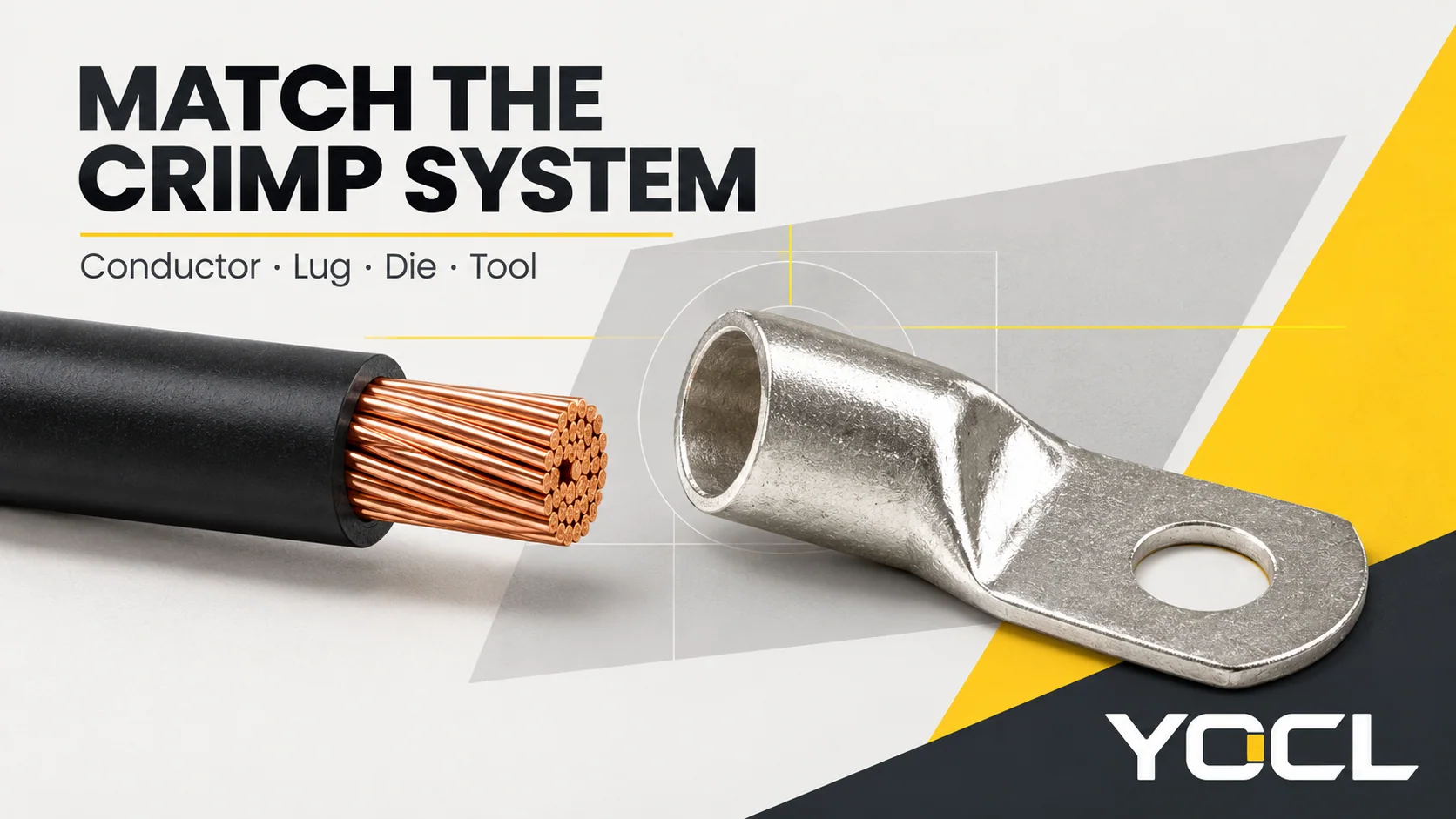
Combine um terminal de compressão através de uma combinação documentada da especificação do condutor, série exata do terminal, matriz de cravação e ferramenta. Em seguida, confirme as instruções de preparação, cravação e inspeção para essa combinação. Um número de tamanho, cor, forma de matriz ou etiqueta de força da ferramenta correspondentes não são suficientes por si só.
O resultado deve ser uma combinação rastreável que possa entregar à pessoa que realiza a terminação. Se a informação de ferramentas aplicável estiver em falta, mantenha a combinação em espera em vez de escolher a matriz mais próxima.
Este é um fluxo de trabalho de verificação de compatibilidade antes da cravação. O trabalho em condutores instalados requer o procedimento de isolamento aplicável e pessoal qualificado. Em locais de trabalho U.S, OSHA 1910.333 aborda a desenergização, bloqueio/sinalização e verificação da condição desenergizada. Este artigo não fornece um método de trabalho em tensão.
Pontos-chave
- Registe o material do condutor, a secção transversal nominal e a construção, e verifique se o terminal exato os aceita.
- Identifique a série do terminal e o seu modelo. Códigos semelhantes podem aparecer em diferentes designs de corpo.
- Encontre a matriz documentada e a ferramenta combinação; o tamanho ou a cor de uma matriz só é útil dentro do seu sistema de identificação.
- Obtenha a preparação necessária, os locais de crimpagem e as verificações de aceitação antes de começar. Mantenha as informações em falta visíveis no registo do trabalho.
- Um ciclo de ferramenta completo ou uma crimpagem de aspeto arrumado não estabelece, por si só, uma terminação aceitável.
Verifique quatro ligações de compatibilidade
Trate a compatibilidade da matriz de crimpagem de terminais de cabo como quatro verificações ligadas. A conclusão de uma não resolve as outras.
| Link de compatibilidade | Evidência para corresponder | Segure o trabalho quando… |
|---|---|---|
| Condutor → corpo do terminal | Material do cabo, tamanho nominal e construção em relação à especificação exata do condutor aceite pelo terminal | O cabo encaixa fisicamente, mas o seu material ou construção não está confirmado |
| Corpo do terminal → matriz | Série/modelo de terminal aplicável e o identificador de matriz especificado ou sistema de matriz permitido | Apenas um tamanho, cor ou forma de cavidade semelhante está disponível |
| Matriz → ferramenta de cravação | Modelo exato da ferramenta/cabeça, família de matrizes e qualquer adaptador ou configuração de funcionamento especificados | A matriz pode ser inserida, mas a combinação documentada está em falta |
| Palma do terminal → equipamento | Disposição do terminal, opção de orifício, ajuste da palma e instruções do equipamento necessários | Um corpo adequado tem uma ligação ao equipamento inadequada |
Para U.S. instalações no local de trabalho, OSHA 1910.303 exige que os conectores sejam identificados quanto ao material do condutor e que o equipamento listado ou rotulado seja utilizado de acordo com as instruções incluídas. Estes são requisitos específicos da jurisdição; utilize as regras aplicáveis do projeto noutros locais.
Passo 1: Registe o condutor antes de escolher a bucha
Comece com a folha de dados do cabo ou identificação fiável do condutor. Registe:
- Material: cobre, alumínio ou outra construção explicitamente identificada.
- Tamanho nominal: retain the stated mm² or American Wire Gauge (AWG) designation.
- Construção: the declared conductor class or strand configuration, including compact or sector-shaped construction where relevant.
- Any termination-relevant finish or treatment identified in the cable documentation.
Do not treat outside cable diameter as conductor area. The insulation diameter describes the cable envelope; nominal conductor area describes the conducting material. Likewise, an approximate AWG-to-mm² conversion does not establish that a connector accepts a substituted size.
When a lug document says only “stranded copper,” resolve any uncertainty about the actual strand construction before proceeding. Do not assume that a fine-stranded flexible conductor, a compact conductor and a conventional stranded conductor are interchangeable because their nominal areas match.
Resultado esperado: one identifiable cable specification that can be compared with the lug documentation. If the conductor construction is unknown, request the cable data rather than selecting a barrel by trial fit.
Step 2: Identify the exact lug series and both interfaces
Record the manufacturer, series, full model and any hole or barrel option. Keep the packaging or batch identification with the job when available.
A tubular compression lug has two distinct interfaces. The barrel receives the conductor; the palm connects to the equipment. The visible form of YOCL SC(JGA) terminais de cobre illustrates this separation, but a product photograph does not supply the tooling specification.
Utilizar o Tabela de Tamanhos de Terminais de Cabo to interpret barrel and mounting dimensions. Keep that mechanical-fit check separate from the documented conductor and tooling match.
A shared model code does not establish a shared die
YOCL publishes both DIN AUS and AUS Thickened copper lug series. Their AUS-16 rows list different barrel dimensions:
| Dimensão publicada | DIN AUS, AUS-16 | AUS Thickened, AUS-16 |
|---|---|---|
| Barrel outside diameter, D | 8 mm | 8.5 mm |
| Barrel bore, d | 6.2 mm | 5.9 mm |
Sources: current YOCL product tables for DIN AUS e AUS Espessado, checked 24 October 2026. These are first-party dimensional declarations, not independent test results.
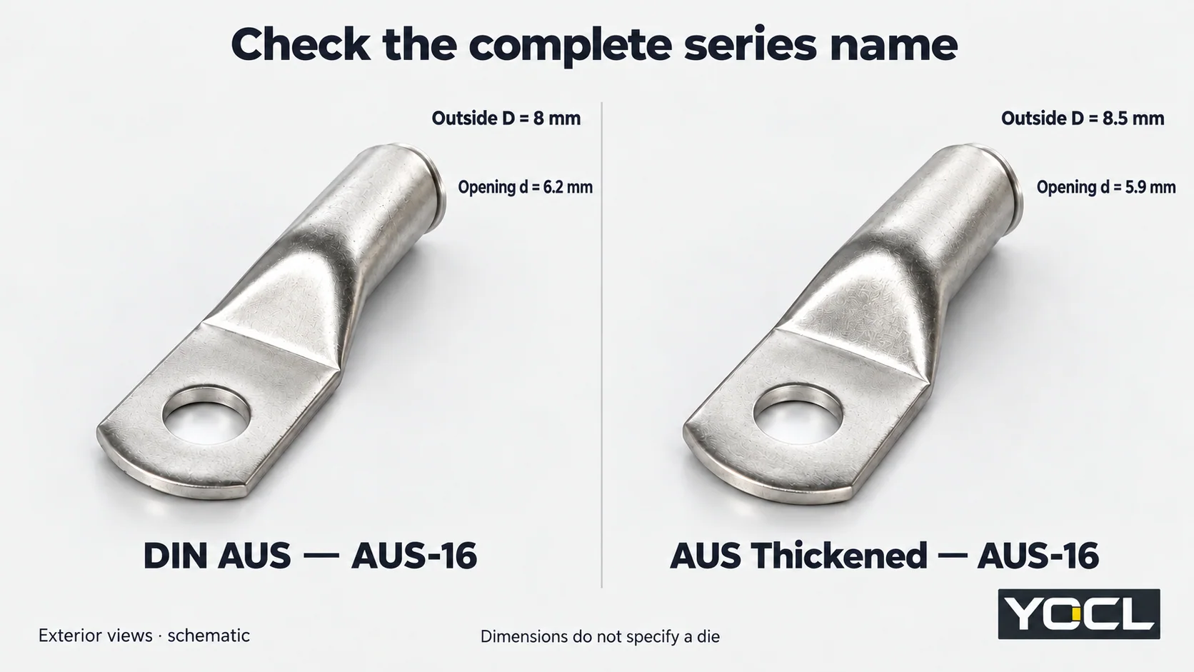
This comparison does not tell you which die to use. It shows why the series name matters. Neither the model suffix nor these dimensions alone establish a permitted conductor area, die cavity or crimping process. Do not calculate a die selection from D or d, or transfer a tooling row from one series to the other without supporting documentation.
Resultado esperado: an exact lug identity with confirmed conductor acceptance and a mechanically suitable equipment interface. For the separate material-transition decision, use Lugs de Cabo de Cobre vs Alumínio vs Bimetálicos.
Step 3: Find the applicable lug–die–tool combination
Obtain the connector manufacturer’s installation instructions, tooling chart or other applicable documented combination. Check its revision and whether it covers the exact lug and conductor identified above.
Read the relevant row across all of its columns and footnotes. The information may include:
| Campo | O que verificar |
|---|---|
| Lug identity | Exact series/model and any barrel or material restriction |
| Condutor | Accepted material, size and construction |
| Ferramenta | Full tool/head designation and permitted configuration |
| Die | Identifier, family, profile and any upper/lower pairing or adapter requirement |
| Process | Required preparation and the specified crimp count, positions or sequence |
| Acceptance | Required inspection, checks and associated records |
If the information is split between a lug instruction and a tool manual, verify that the documents refer to a permitted common combination. A tool’s broad cable-size range describes its stated capability; it does not approve every lug within that numerical range.
An equipment example illustrates why instructions matter: the UL Solutions Deadfront Switchboard Application Guide describes necessary special-tool instructions for certain field-wiring pressure connectors and identification of acceptable terminal assemblies. Its scope is certified deadfront switchboards, and its stated National Electrical Code references are to the 2020 edition. It is not a universal lug tooling chart.
Use markings to locate the instructions
A colour band or die index can help identify a component within the system that defines it. Use it to locate the applicable tooling information. Do not assume the same colour, number or “hex” description means the same combination across brands or series.
Similarly, the force shown on a hydraulic tool does not identify the required die and lug combination. A dieless tool also needs documented applicability; the absence of a removable die does not remove the compatibility check.
Se for proposta uma ferramenta ou matriz alternativa, solicite documentação que cubra essa combinação exata. O encaixe físico na cabeça da ferramenta, a aparência semelhante e um teste de aperto bem-sucedido não substituem a correspondência em falta.
Resultado esperado: uma referência de instrução gravada que ligue o condutor, terminal, matriz e ferramenta reais. Se alguma ligação permanecer não confirmada, não prossiga com a cravação.
Passo 4: Resolva as instruções do processo antes de começar
A compatibilidade inclui a forma como a combinação é utilizada. Antes de preparar o condutor, identifique as instruções aplicáveis para:
- descascamento e preparação do condutor;
- inserção e qualquer método de verificação da mesma;
- tratamento de superfície ou composto, quando especificado;
- orientação da matriz e os locais, contagem e sequência de crimpagem necessários;
- conclusão do ciclo da ferramenta e verificações do estado da ferramenta;
- inspeção e qualquer qualificação ou teste de amostra necessário.
O comprimento da cavidade do corpo não é automaticamente o comprimento de descapagem. Um corpo mais longo não requer automaticamente uma crimpagem extra, e uma área plana visualmente ampla não identifica onde a matriz deve atuar. Obtenha as instruções reais para essas decisões.
Não corte fios, não dobre o condutor, não adicione enchimento, não mude uma matriz nem adicione outra compressão para compensar uma incompatibilidade não resolvida. Pare e obtenha uma solução instruída. Essas alterações modificam a terminação que deveria verificar.
Se a verificação de condição ou o estado de serviço exigido pela ferramenta não estiverem resolvidos, reserve-a até que as instruções da ferramenta e o seu processo de qualidade sejam satisfeitos. Não invente um intervalo de calibração comum para cada ferramenta hidráulica, mecânica ou a bateria.
Resultado esperado: o operador tem um processo aplicável e critérios de aceitação antes da primeira crimpagem de produção. Este artigo fornece a sequência de verificação; a preparação real e a operação da ferramenta provêm dessas instruções.
Passo 5: Separar a conclusão da ferramenta, inspeção e restauração
Após a realização do processo de crimpagem documentado, verifique o trabalho em relação aos seus critérios de aceitação especificados. Três perguntas permanecem distintas:
| Verificar | O que estabelece | O que não estabelece sozinho |
|---|---|---|
| Was the specified tool cycle completed? | The recorded tool operation reached its prescribed end state | That the conductor, lug and die were correctly matched |
| Does the termination meet its inspection criteria? | The required visible features and other specified checks were assessed | Unspecified electrical performance or certification |
| Is the equipment termination ready for service? | The equipment-side connection and required installation checks are complete | Automatic restoration authorization from the crimp’s appearance |
Inspect the features required by the instruction, such as insertion evidence, conductor condition, crimp position and any specified identifying impression. A neat hexagonal outline cannot establish all of these. A hand tug is not a substitute for a specified pull test or its acceptance criteria.
Where the applicable quality plan requires sample, destructive or electrical testing, use its method, sampling rules and limits. This workflow supplies no universal pull force, resistance threshold or number of test samples.
If a termination fails inspection, segregate it and follow the authorized disposition. Do not assume that another squeeze will repair it. Replacement, rework or further assessment depends on the actual instructions and condition.
The palm-to-equipment connection still needs the specified hardware, arrangement and fastening instructions. Restore service only through the equipment’s authorized procedure after the required checks are complete.
Keep a match record with the termination job
Use this record for each distinct combination. Link it to the relevant work order or termination schedule so an inspector can trace the installed parts to the instructions used.
| Campo do registo | Entry to retain |
|---|---|
| Cabo | Manufacturer/type, material, nominal size and declared construction |
| Lug | Manufacturer, exact series/model, relevant option and batch identification where available |
| Tool and head | Exact model/configuration and equipment identity |
| Die or dieless setting | Required identification/configuration from the applicable instructions |
| Authority for the match | Document title, revision, page/table/row and any footnote |
| Process requirements | Preparation, crimp locations/count/sequence and specified tool checks |
| Requisitos de aceitação | Inspection criteria and any required test/qualification reference |
| Job result | Operator/inspector record, required results and unresolved deviations |
Use clear decisions:
- Hold: a required specification, documented combination, instruction or tool condition is missing.
- Refer for review: documents conflict or a substitute component/process is proposed.
- Ready for the documented crimping process: the matching and prerequisite checks are complete. This does not mean the finished joint has already passed inspection.
For help identifying the relevant YOCL cable lug family, send the exact lug series/model, cable datasheet, proposed die and tool models, and equipment connection drawing. Request the applicable conductor acceptance and tooling instructions before authorizing the termination. For product orientation, return to O que é um Terminal de Cabo?.
Leitura relacionada: Ver installing wire ferrules.
Leitura relacionada: cable lug connection overheating checks.
Referências
- OSHA — 29 CFR 1910.333: Seleção e uso de práticas de trabalho, particularly deenergization and verification provisions; U.S. workplace context.
- OSHA — 29 CFR 1910.303: Geral, paragraphs (b)(2) and (c)(1); U.S. instruction and conductor-material requirements.
- YOCL ELECTRIC — SC(JGA) terminais de cobre; first-party exterior barrel/palm product information and cover reference.
- YOCL ELECTRIC — DIN AUS copper cable lugs; first-party AUS-16 dimensional data, checked 24 October 2026.
- YOCL ELECTRIC — AUS Thickened copper cable lugs; first-party AUS-16 dimensional data, checked 24 October 2026.
- UL Soluções — Guia de Aplicação para Quadros Elétricos Deadfront, Wiring terminals and application scope; equipment example, with stated NEC references to the 2020 edition.