
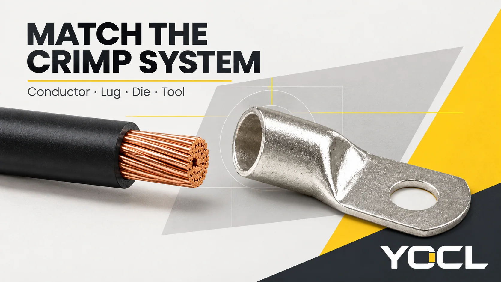
Match a compression cable lug through a documented combination of conductor specification, exact lug series, crimp die and tool. Then confirm the preparation, crimping and inspection instructions for that combination. A matching size number, colour, die shape or tool-force label is insufficient on its own.
The result should be a traceable match you can hand to the person performing the termination. If the applicable tooling information is missing, keep the combination on hold rather than choosing the nearest die.
This is a compatibility-check workflow before crimping. Work on installed conductors requires the applicable isolation procedure and qualified personnel. In U.S. workplaces, OSHA 1910.333 addresses deenergization, lockout/tagout and verification of the deenergized condition. This article does not provide an energized-work method.
Key Takeaways
- Record conductor material, nominal cross-section and construction, then verify that the exact lug accepts them.
- Identify the lug series as well as its model. Similar codes can appear on different barrel designs.
- Find the documented die and tool combination; a die’s size or colour is only useful within its identification system.
- Obtain the required preparation, crimp locations and acceptance checks before starting. Keep missing information visible in the job record.
- A completed tool cycle or tidy-looking crimp does not, by itself, establish an acceptable termination.
Check four compatibility links
Treat cable lug crimp die compatibility as four connected checks. Completing one does not resolve the others.
| Compatibility link | Evidence to match | Hold the job when… |
|---|---|---|
| Conductor → lug barrel | Cable material, nominal size and construction against the exact lug’s accepted conductor specification | The cable fits physically, but its material or construction is not confirmed |
| Lug barrel → die | Applicable lug series/model and the specified die identifier or permitted die system | Only a similar size, colour or cavity shape is available |
| Die → crimping tool | Exact tool/head model, die family and any specified adapter or operating configuration | The die can be inserted, but the documented combination is missing |
| Lug palm → equipment | Required terminal arrangement, hole option, palm fit and equipment instructions | A suitable barrel has an unsuitable equipment connection |
For U.S. workplace installations, OSHA 1910.303 requires connectors to be identified for the conductor material and listed or labelled equipment to be used according to its included instructions. These are jurisdiction-specific requirements; use the applicable project rules elsewhere.
Step 1: Record the conductor before choosing the lug
Start with the cable datasheet or reliable conductor identification. Record:
- Material: copper, aluminium or another explicitly identified construction.
- Nominal size: retain the stated mm² or American Wire Gauge (AWG) designation.
- Construction: the declared conductor class or strand configuration, including compact or sector-shaped construction where relevant.
- Any termination-relevant finish or treatment identified in the cable documentation.
Do not treat outside cable diameter as conductor area. The insulation diameter describes the cable envelope; nominal conductor area describes the conducting material. Likewise, an approximate AWG-to-mm² conversion does not establish that a connector accepts a substituted size.
When a lug document says only “stranded copper,” resolve any uncertainty about the actual strand construction before proceeding. Do not assume that a fine-stranded flexible conductor, a compact conductor and a conventional stranded conductor are interchangeable because their nominal areas match.
Expected result: one identifiable cable specification that can be compared with the lug documentation. If the conductor construction is unknown, request the cable data rather than selecting a barrel by trial fit.
Step 2: Identify the exact lug series and both interfaces
Record the manufacturer, series, full model and any hole or barrel option. Keep the packaging or batch identification with the job when available.
A tubular compression lug has two distinct interfaces. The barrel receives the conductor; the palm connects to the equipment. The visible form of YOCL SC(JGA) copper cable lugs illustrates this separation, but a product photograph does not supply the tooling specification.
Use the Cable Lug Size Chart to interpret barrel and mounting dimensions. Keep that mechanical-fit check separate from the documented conductor and tooling match.
A shared model code does not establish a shared die
YOCL publishes both DIN AUS and AUS Thickened copper lug series. Their AUS-16 rows list different barrel dimensions:
| Published dimension | DIN AUS, AUS-16 | AUS Thickened, AUS-16 |
|---|---|---|
| Barrel outside diameter, D | 8 mm | 8.5 mm |
| Barrel bore, d | 6.2 mm | 5.9 mm |
Sources: current YOCL product tables for DIN AUS and AUS Thickened, checked 24 October 2026. These are first-party dimensional declarations, not independent test results.
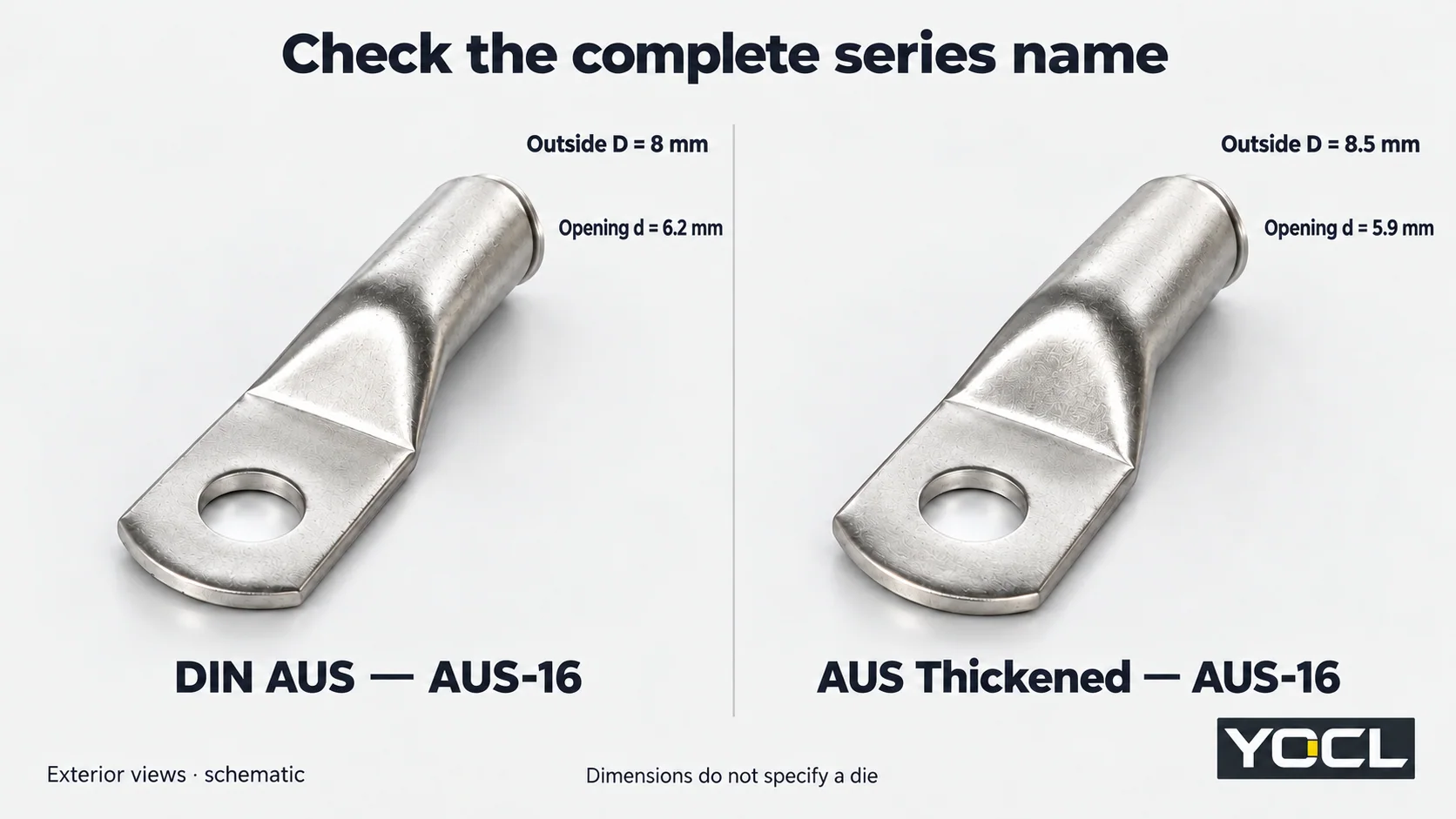
This comparison does not tell you which die to use. It shows why the series name matters. Neither the model suffix nor these dimensions alone establish a permitted conductor area, die cavity or crimping process. Do not calculate a die selection from D or d, or transfer a tooling row from one series to the other without supporting documentation.
Expected result: an exact lug identity with confirmed conductor acceptance and a mechanically suitable equipment interface. For the separate material-transition decision, use Copper vs Aluminium vs Bimetallic Cable Lugs.
Step 3: Find the applicable lug–die–tool combination
Obtain the connector manufacturer’s installation instructions, tooling chart or other applicable documented combination. Check its revision and whether it covers the exact lug and conductor identified above.
Read the relevant row across all of its columns and footnotes. The information may include:
| Field | What to verify |
|---|---|
| Lug identity | Exact series/model and any barrel or material restriction |
| Conductor | Accepted material, size and construction |
| Tool | Full tool/head designation and permitted configuration |
| Die | Identifier, family, profile and any upper/lower pairing or adapter requirement |
| Process | Required preparation and the specified crimp count, positions or sequence |
| Acceptance | Required inspection, checks and associated records |
If the information is split between a lug instruction and a tool manual, verify that the documents refer to a permitted common combination. A tool’s broad cable-size range describes its stated capability; it does not approve every lug within that numerical range.
An equipment example illustrates why instructions matter: the UL Solutions Deadfront Switchboard Application Guide describes necessary special-tool instructions for certain field-wiring pressure connectors and identification of acceptable terminal assemblies. Its scope is certified deadfront switchboards, and its stated National Electrical Code references are to the 2020 edition. It is not a universal lug tooling chart.
Use markings to locate the instructions
A colour band or die index can help identify a component within the system that defines it. Use it to locate the applicable tooling information. Do not assume the same colour, number or “hex” description means the same combination across brands or series.
Similarly, the force shown on a hydraulic tool does not identify the required die and lug combination. A dieless tool also needs documented applicability; the absence of a removable die does not remove the compatibility check.
If an alternative tool or die is proposed, ask for documentation covering that exact combination. Physical fit in the tool head, similar appearance and a successful practice squeeze are not substitutes for the missing match.
Expected result: a recorded instruction reference linking the actual conductor, lug, die and tool. If any link remains unconfirmed, do not release the job for crimping.
Step 4: Resolve the process instructions before starting
Compatibility includes how the combination is used. Before preparing the conductor, identify the applicable instructions for:
- stripping and conductor preparation;
- insertion and any method of verifying it;
- surface treatment or compound, where specified;
- die orientation and the required crimp locations, count and sequence;
- tool-cycle completion and tool condition checks;
- inspection and any required qualification or sample testing.
A barrel cavity length is not automatically the strip length. A longer barrel does not automatically require an extra crimp, and a visually broad flat area does not identify where the die should act. Obtain the actual instructions for those decisions.
Do not trim strands, fold the conductor, add filler, change a die or add another compression to compensate for an unresolved mismatch. Stop and obtain an instructed solution. These changes alter the termination you were supposed to verify.
If the tool’s required condition check or service status is unresolved, set it aside until the tool instructions and your quality process are satisfied. Do not invent a common calibration interval for every hydraulic, mechanical or battery tool.
Expected result: the operator has an applicable process and acceptance criteria before the first production crimp. This article supplies the verification sequence; the actual preparation and tool operation come from those instructions.
Step 5: Separate tool completion, inspection and restoration
After the documented crimping process is performed, check the work against its specified acceptance criteria. Three questions remain distinct:
| Check | What it establishes | What it does not establish alone |
|---|---|---|
| Was the specified tool cycle completed? | The recorded tool operation reached its prescribed end state | That the conductor, lug and die were correctly matched |
| Does the termination meet its inspection criteria? | The required visible features and other specified checks were assessed | Unspecified electrical performance or certification |
| Is the equipment termination ready for service? | The equipment-side connection and required installation checks are complete | Automatic restoration authorization from the crimp’s appearance |
Inspect the features required by the instruction, such as insertion evidence, conductor condition, crimp position and any specified identifying impression. A neat hexagonal outline cannot establish all of these. A hand tug is not a substitute for a specified pull test or its acceptance criteria.
Where the applicable quality plan requires sample, destructive or electrical testing, use its method, sampling rules and limits. This workflow supplies no universal pull force, resistance threshold or number of test samples.
If a termination fails inspection, segregate it and follow the authorized disposition. Do not assume that another squeeze will repair it. Replacement, rework or further assessment depends on the actual instructions and condition.
The palm-to-equipment connection still needs the specified hardware, arrangement and fastening instructions. Restore service only through the equipment’s authorized procedure after the required checks are complete.
Keep a match record with the termination job
Use this record for each distinct combination. Link it to the relevant work order or termination schedule so an inspector can trace the installed parts to the instructions used.
| Record field | Entry to retain |
|---|---|
| Cable | Manufacturer/type, material, nominal size and declared construction |
| Lug | Manufacturer, exact series/model, relevant option and batch identification where available |
| Tool and head | Exact model/configuration and equipment identity |
| Die or dieless setting | Required identification/configuration from the applicable instructions |
| Authority for the match | Document title, revision, page/table/row and any footnote |
| Process requirements | Preparation, crimp locations/count/sequence and specified tool checks |
| Acceptance requirements | Inspection criteria and any required test/qualification reference |
| Job result | Operator/inspector record, required results and unresolved deviations |
Use clear decisions:
- Hold: a required specification, documented combination, instruction or tool condition is missing.
- Refer for review: documents conflict or a substitute component/process is proposed.
- Ready for the documented crimping process: the matching and prerequisite checks are complete. This does not mean the finished joint has already passed inspection.
For help identifying the relevant YOCL cable lug family, send the exact lug series/model, cable datasheet, proposed die and tool models, and equipment connection drawing. Request the applicable conductor acceptance and tooling instructions before authorizing the termination. For product orientation, return to What Is a Cable Lug?.
Related reading: See installing wire ferrules.
Related reading: cable lug connection overheating checks.
References
- OSHA — 29 CFR 1910.333: Selection and use of work practices, particularly deenergization and verification provisions; U.S. workplace context.
- OSHA — 29 CFR 1910.303: General, paragraphs (b)(2) and (c)(1); U.S. instruction and conductor-material requirements.
- YOCL ELECTRIC — SC(JGA) copper cable lugs; first-party exterior barrel/palm product information and cover reference.
- YOCL ELECTRIC — DIN AUS copper cable lugs; first-party AUS-16 dimensional data, checked 24 October 2026.
- YOCL ELECTRIC — AUS Thickened copper cable lugs; first-party AUS-16 dimensional data, checked 24 October 2026.
- UL Solutions — Deadfront Switchboard Application Guide, Wiring terminals and application scope; equipment example, with stated NEC references to the 2020 edition.