
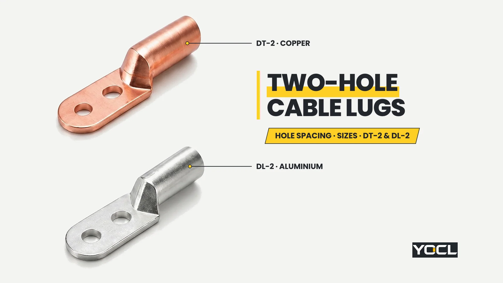
Terminais de cabo de dois furos são terminais tubulares de compressão construídos com um corpo para o condutor e uma patilha de montagem plana estendida, perfurada com dois furos para parafusos alinhados, bloqueando a orientação angular da patilha em terminais de equipamento de dois pernos e barramentos. Em todas as séries de cobre DT-2 e alumínio DL-2 da YOCL ELECTRIC, os modelos 27 abrangem 16–630 mm².
Especificar uma patilha de dois furos requer mais do que corresponder a uma secção transversal de cabo e a um diâmetro de parafuso. Como dois parafusos passam pela mesma patilha rígida, o terminal apenas encaixa no terminal do equipamento quando tanto o diâmetro do furo de montagem Φ como o espaçamento entre centros dos furos L3 correspondem simultaneamente ao padrão de furos do terminal. Para manter os tópicos vizinhos distintos, as dimensões dos terminais de um furo e gerais pertencem a a tabela de tamanhos de terminais de cabo, a correspondência entre metais do condutor e do terminal pertence a terminais de cabo de cobre vs alumínio vs bimetálicos, a preparação da união para corpos de alumínio pertence a composto antioxidante para terminais de alumínio, e a ferramenta de compressão pertence a como combinar terminais de cabo, matrizes de crimpagem e condutores.
O que é um terminal de cabo de dois furos: bloqueio de orientação vs rotação de parafuso único
Um terminal de cabo de dois furos combina um corpo cilíndrico para o condutor com uma aba plana alongada que possui dois furos de montagem alinhados. O segundo furo não é um ponto de fixação sobressalente: apertar dois parafusos ao longo da linha central da aba fixa a orientação da aba e elimina a liberdade de rotação em torno do eixo do parafuso.
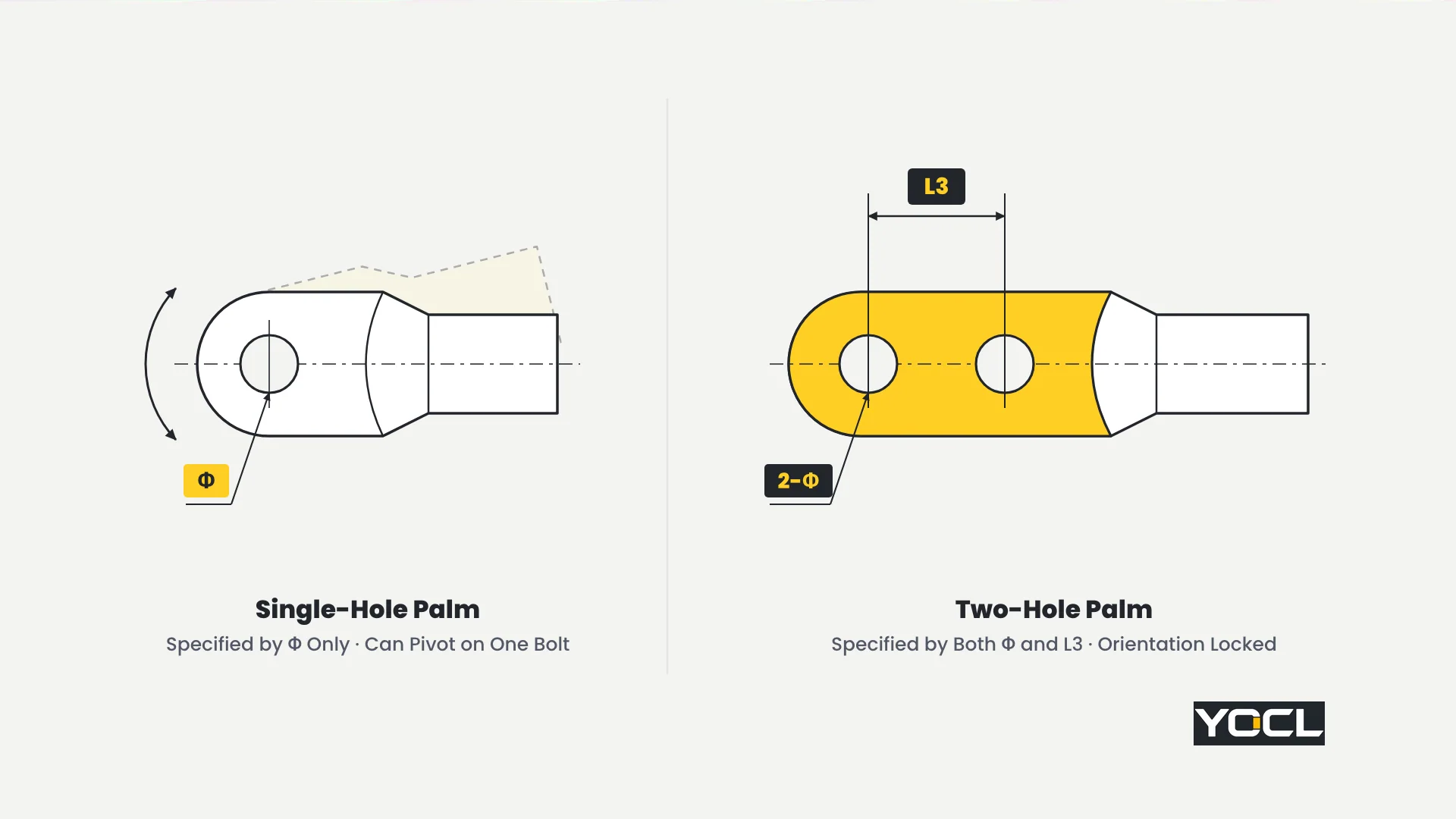
Do ponto de vista geométrico e de instalação, comparar uma aba de um parafuso com uma aba de dois parafusos explica por que são usados dois pontos de fixação em terminações maiores:
- Por que uma aba de um parafuso pode rodar: Um único furo de montagem restringe o movimento através da face da aba, mas deixa um grau de liberdade de rotação em torno do eixo do parafuso. Sob a rigidez de flexão de um cabo de potência pesado, carga lateral durante a organização da instalação, ou um parafuso que perdeu a força de aperto, uma aba de um parafuso pode girar lateralmente em torno do seu perno.
- Como dois parafusos eliminam a liberdade de rotação: Adicionar um segundo orifício de montagem a uma distância entre centros L3 estabelece uma restrição linear de dois pontos. Com ambos os parafusos instalados, a patilha não pode rodar em direção a barras de fase adjacentes, paredes de invólucros ou terminais vizinhos.
- Apenas geometria e prática de instalação: As páginas de produto da YOCL indicam a configuração estrutural — um corpo para condutor, dois orifícios de montagem e a ligação pretendida de um condutor de cobre ou alumínio a um terminal de equipamento elétrico — sem publicar dados comparativos de vibração, extração, binário ou corrente. Considere a patilha de dois orifícios estritamente como uma geometria de fixação de orientação e correspondência de terminal.
A Diferença na Especificação: Correspondência do Diâmetro do Orifício (Φ) e do Espaçamento entre Centros (L3)
Enquanto uma patilha de terminal de um orifício é especificada por uma única dimensão de ajuste — o seu diâmetro de orifício de montagem —, uma patilha de terminal de dois orifícios é especificada por duas dimensões de ajuste obrigatórias em simultâneo: diâmetro individual do orifício Φ e espaçamento entre centros dos orifícios L3. Ambos os valores devem corresponder ao padrão de furação do terminal do equipamento.
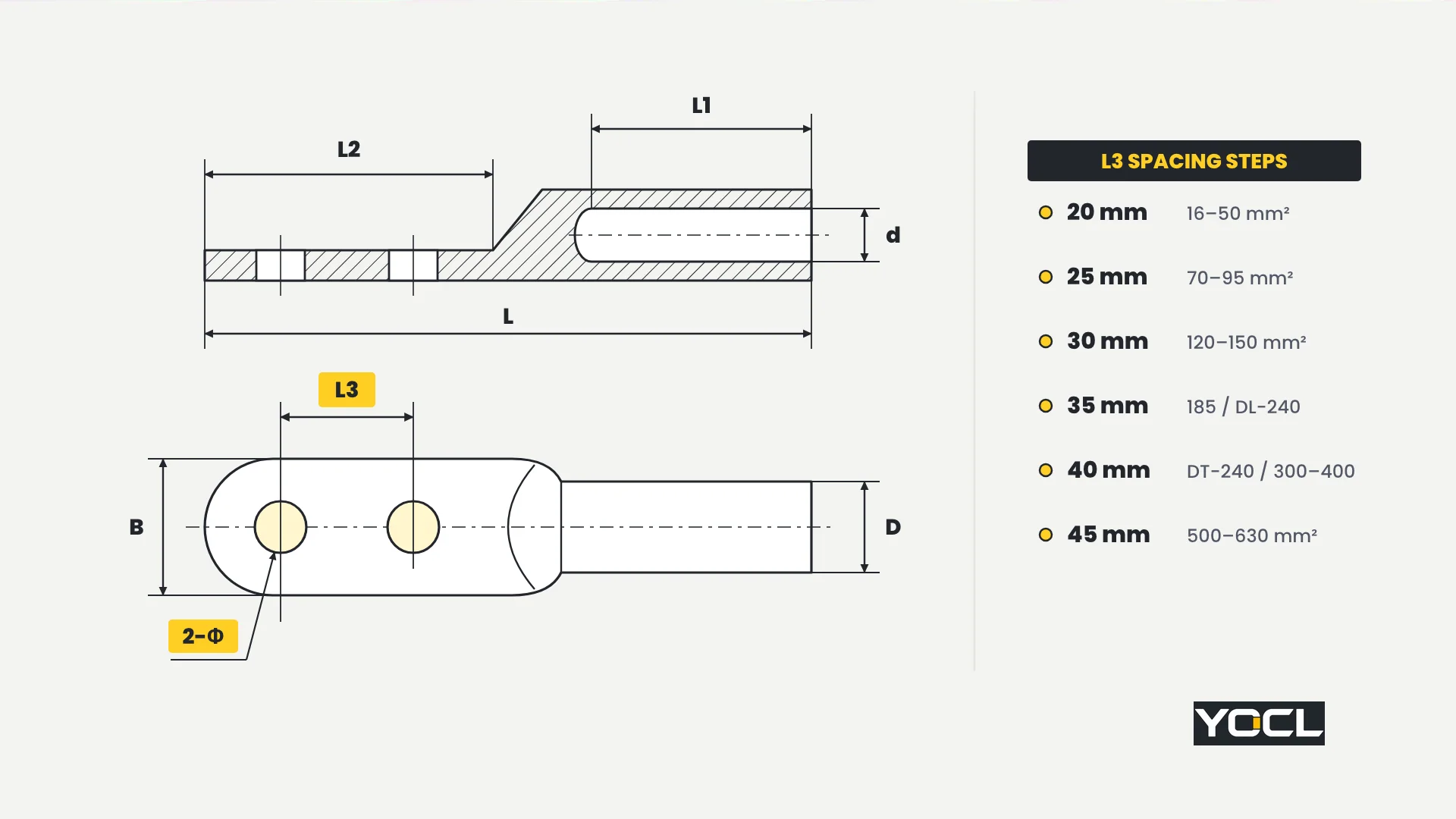
Quatro regras regem todas as especificações de terminais de dois furos:
- Definições dos campos do desenho: Em ambas as páginas de produto YOCL, Φ é o diâmetro de cada orifício de montagem, L3 é o espaçamento entre centros dos dois orifícios, D é o diâmetro exterior do corpo, d é o diâmetro interno do cilindro, B é a largura da palma, e L, L1, e L2 follow the overall, barrel, and palm length callouts on the page drawings. Every dimension is in millimetres, and the model suffix is the conductor size in mm².
- L3 steps in six discrete increments: Across both the DT-2 and DL-2 ranges, L3 is not continuous and is not fixed at one universal pitch. As conductor cross-section grows, L3 steps through 20 mm, 25 mm, 30 mm, 35 mm, 40 mm, e 45 mm.
- A 5 mm L3 mismatch does not fit at all: If a lug’s hole diameter Φ matches the terminal studs but its centre spacing L3 is even 5 mm off—such as a 35 mm spacing palm held against a 40 mm spacing busbar—the second bolt cannot enter the hole.
- Order by the terminal pattern, not by conductor size alone: A lug with the wrong L3 cannot be “made to fit” without re-drilling or slotting the palm, which modifies the lug outside the product as supplied. Always check the equipment terminal’s hole diameter and centre-to-centre spacing before ordering.
Two-Hole Cable Lugs Size Charts: YOCL DT-2 Copper and DL-2 Aluminium Series
Especificação two-hole cable lugs from YOCL ELECTRIC requires checking the exact table for your conductor material: DT-2 for copper conductors (13 models, 25–630 mm²) and DL-2 for aluminium conductors (14 models, 16–630 mm²). Never merge the two charts or use one material’s row for the other.
Table A: DT-2 Two-Hole Copper Cable Lugs (25–630 mm², 13 Models)
YOCL’s DT-2 two-hole copper cable lugs are copper compression lugs with one conductor barrel and two mounting holes, designed to connect copper conductors (25–630 mm²) to electrical equipment terminals.
Across the 13 DT-2 models, hole diameter Φ steps through 8.5, 10.5, 12.5, 14.5, 16.5, e 21 mm, while centre-to-centre spacing L3 steps through 20, 25, 30, 35, 40, e 45 mm.
| Modelo | Φ (mm) | D (mm) | d (mm) | L (mm) | L1 (mm) | L2 (mm) | L3 (mm) | B (mm) |
|---|---|---|---|---|---|---|---|---|
| DT-2-25 | 8.5 | 11 | 7.8 | 86 | 32 | 40 | 20 | 18 |
| DT-2-35 | 10.5 | 12 | 8.7 | 98 | 34 | 47 | 20 | 20 |
| DT-2-50 | 10.5 | 14 | 9.7 | 105 | 40 | 50 | 20 | 23 |
| DT-2-70 | 12.5 | 16 | 12 | 118 | 45 | 55 | 25 | 26 |
| DT-2-95 | 12.5 | 18 | 13.5 | 125 | 48 | 57 | 25 | 28 |
| DT-2-120 | 14.5 | 20 | 15.5 | 135 | 50 | 65 | 30 | 30 |
| DT-2-150 | 14.5 | 22 | 16.5 | 142 | 53 | 68 | 30 | 34 |
| DT-2-185 | 14.5 | 25 | 18.5 | 145 | 55 | 71 | 35 | 37 |
| DT-2-240 | 16.5 | 27 | 21 | 160 | 59 | 74 | 40 | 40 |
| DT-2-300 | 16.5 | 30 | 23 | 172 | 62 | 81 | 40 | 45 |
| DT-2-400 | 16.5 | 34 | 26 | 181 | 68 | 82 | 40 | 50 |
| DT-2-500 | 21 | 38 | 29.5 | 203 | 73 | 96 | 45 | 60 |
| DT-2-630 | 21 | 45 | 35 | 220 | 84 | 107 | 45 | 60 |
Regra de Seleção: Use Table A (DT-2) exclusively for copper conductors (25–630 mm²), confirming that Φ, L3, and palm width B match the equipment terminal drawing.
Table B: DL-2 Two-Hole Aluminium Cable Lugs (16–630 mm², 14 Models)
YOCL’s DL-2 two-hole aluminium cable lugs are aluminium compression lugs with one conductor barrel and two mounting holes, designed to connect aluminium conductors (16–630 mm²) to electrical equipment terminals.
The 14-model DL-2 range begins at DL-2-16 (16 mm²) and is not interchangeable with the copper table: barrel diameters D e d, lengths L / L1 / L2, e o 240 mm² e 400 mm² palm hole patterns differ from DT-2. For joint preparation on aluminium barrels, see composto antioxidante para terminais de alumínio.
| Modelo | Φ (mm) | D (mm) | d (mm) | L (mm) | L1 (mm) | L2 (mm) | L3 (mm) | B (mm) |
|---|---|---|---|---|---|---|---|---|
| DL-2-16 | 8.5 | 10 | 5.5 | 93 | 32 | 44 | 20 | 18 |
| DL-2-25 | 8.5 | 12 | 7 | 94 | 33 | 45 | 20 | 18 |
| DL-2-35 | 10.5 | 14 | 8.5 | 104 | 42 | 48 | 20 | 20 |
| DL-2-50 | 10.5 | 16 | 9.5 | 112 | 47 | 50 | 20 | 23 |
| DL-2-70 | 12.5 | 18 | 12 | 125 | 48 | 59 | 25 | 26 |
| DL-2-95 | 12.5 | 21 | 13 | 136 | 53 | 60 | 25 | 28 |
| DL-2-120 | 14.5 | 23 | 15 | 145 | 55 | 69 | 30 | 30 |
| DL-2-150 | 14.5 | 25 | 16 | 150 | 57 | 70 | 30 | 34 |
| DL-2-185 | 14.5 | 27 | 18 | 162 | 63 | 76 | 35 | 37 |
| DL-2-240 | 14.5 | 30 | 20 | 170 | 66 | 77 | 35 | 40 |
| DL-2-300 | 16.5 | 34 | 23 | 180 | 73 | 78 | 40 | 45 |
| DL-2-400 | 21 | 38 | 26 | 195 | 76 | 87 | 40 | 50 |
| DL-2-500 | 21 | 42 | 30 | 205 | 80 | 91 | 45 | 60 |
| DL-2-630 | 21 | 45 | 34.5 | 210 | 85 | 95 | 45 | 60 |
Regra de Seleção: Use Table B (DL-2) exclusively for aluminium conductors (16–630 mm²), and read Φ e L3 directly from the DL-2 row rather than assuming parity with DT-2.
Reading the Charts: Selection Order and Worked Examples
To select the right model without palm-fit errors, follow a strict verification sequence: match conductor size and material to the model first, verify Φ e L3 against the equipment terminal drawing second, and check palm width B against the terminal face third.
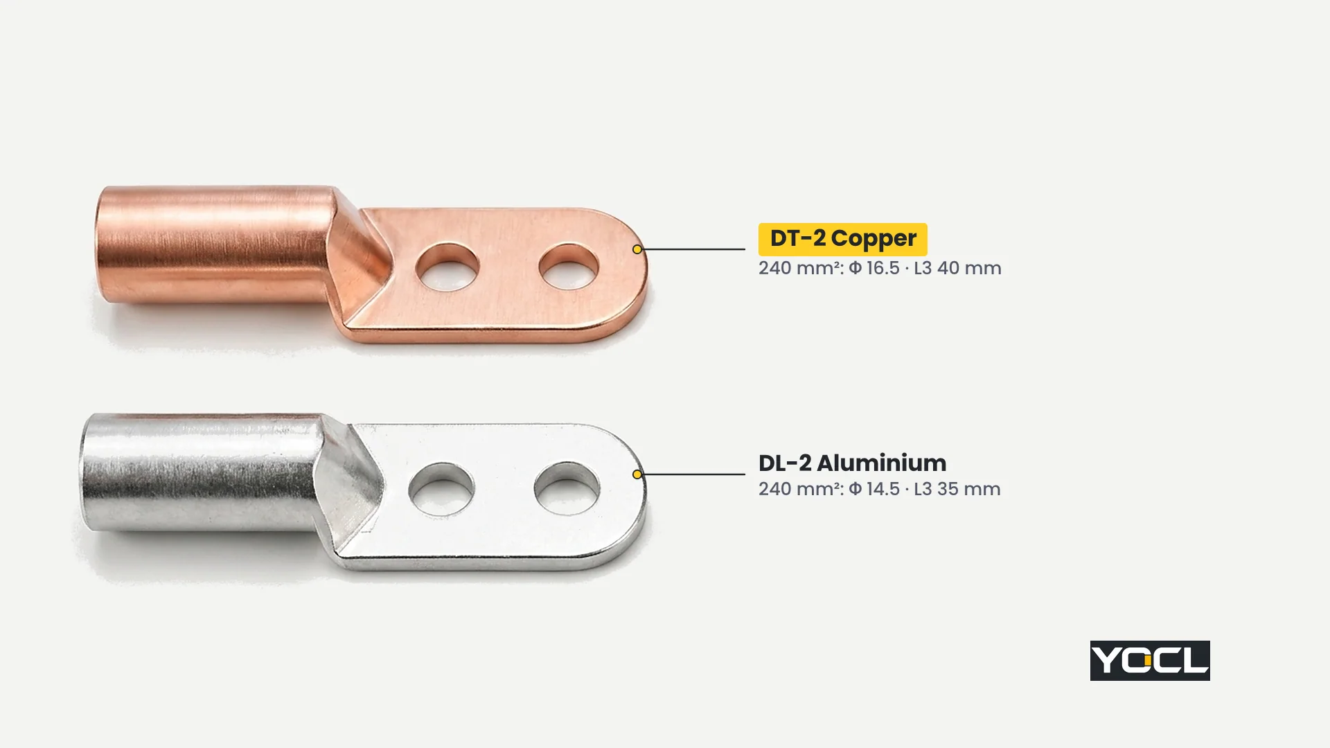
Step-by-Step Selection Order
- Conductor size and material → Model: Pick DT-2 for a copper conductor or DL-2 for an aluminium conductor (never fit an aluminium lug on a copper cable or the reverse; see terminais de cabo de cobre vs alumínio vs bimetálicos) and locate the row matching your conductor cross-section in mm².
- Verify Φ and L3 against the terminal drawing: Check that both the hole diameter Φ como o espaçamento entre centros dos furos L3 in that row match the equipment terminal’s hole pattern.
- Check palm width B against the terminal face: Confirm that B (de 18 mm up to 60 mm) fits cleanly within the terminal pad width and phase barriers.
Worked Examples: 95 mm² Coincidence vs 240 mm² and 400 mm² Divergence
- 95 mm² Copper vs Aluminium (Coincidence of One Row):
A 95 mm² copper conductor terminating on a two-hole pad with 12.5 mm holes at 25 mm centres selects DT-2-95, which has Φ = 12.5 mm, L3 = 25 mm, e B = 28 mm (with D = 18 mm, d = 13.5 mm, L = 125 mm, L1 = 48 mm, L2 = 57 mm). For a 95 mm² aluminium conductor, DL-2-95 happens to share Φ = 12.5 mm, L3 = 25 mm, e B = 28 mm (while its barrel and length dimensions change to D = 21 mm, d = 13 mm, L = 136 mm, L1 = 53 mm, L2 = 60 mm). That palm match at 95 mm² is a coincidence of this row, not a cross-table rule. - 240 mm² Copper vs Aluminium (Both Φ and L3 Diverge):
Em 240 mm², the two materials diverge in both palm fit dimensions. In Table A, DT-2-240 (copper) has Φ = 16.5 mm, D = 27 mm, d = 21 mm, L = 160 mm, L1 = 59 mm, L2 = 74 mm, L3 = 40 mm, e B = 40 mm. In Table B, DL-2-240 (aluminium) has Φ = 14.5 mm, D = 30 mm, d = 20 mm, L = 170 mm, L1 = 66 mm, L2 = 77 mm, L3 = 35 mm, e B = 40 mm. A buyer terminating a 240 mm² aluminium cable must check the DL-2-240 row separately: its 14.5 mm holes at 35 mm centres will not fit a terminal drilled for 16.5 mm holes at 40 mm centres. - 400 mm² Copper vs Aluminium (Hole Diameter Φ Diverges):
Em 400 mm², both rows share L3 = 40 mm e B = 50 mm, but DT-2-400 tem Φ = 16.5 mm (D = 34, d = 26, L = 181, L1 = 68, L2 = 82 mm) whereas DL-2-400 tem Φ = 21 mm (D = 38, d = 26, L = 195, L1 = 76, L2 = 87 mm).
When One Bolt Is Not Enough: How the Terminal and Application Decide
Answering when one bolt is not enough begins with the equipment terminal itself: the terminal as built decides first. A single-hole equipment terminal takes a single-hole lug, and no lug preference overrides the hardware pattern on the equipment.
Where termination geometry is being specified or matched on site, three rules apply:
- The equipment terminal pattern comes first: Two-hole palms belong on equipment terminals and busbar ends that provide a matching two-hole pattern (Φ e L3). Where an equipment stud or busbar pad has only one hole, specify a single-hole lug.
- Where orientation lock matters: Two-hole palms are specified where heavy feeders could twist a single-bolt palm out of alignment during installation pulling, where tight phase-to-phase spacing requires the palm to stay fixed inline with the busbar, or where the equipment manufacturer provides two inline studs to prevent palm rotation.
- Conductor size is a hint, not a current rule: YOCL’s two-hole ranges start at 25 mm² in copper (DT-2) e 16 mm² in aluminium (DL-2) and run to 630 mm², while smaller wire sizes are covered by single-hole ranges (see a tabela de tamanhos de terminais de cabo). Do not apply an assumed current threshold for switching to two holes—the product pages publish no current ratings for these series.
Installation Notes: Both Bolts Installed and Pre-Crimp Spacing Checks
Installing a two-hole lug requires two field habits that follow directly from the data: every two-hole palm must be fastened with both bolts, and L3 must be verified against the terminal before the barrel is crimped onto the cable.
- Both bolts belong to the joint: Fitting only one bolt of a two-hole palm into a single-hole terminal leaves the palm free to rotate around that single bolt—the exact failure mode the second hole exists to prevent—while leaving half of the palm overhanging the contact pad.
- Check L3 before crimping: Verify Φ e L3 on the terminal drawing or by measuring centre-to-centre directly on the terminal pad before crimping. After compression, a lug with the wrong hole spacing cannot be exchanged without cutting the conductor back.
- Use the matching crimp die: Match the compression die to the barrel’s series and size (D e d differ between DT-2 and DL-2); see como combinar terminais de cabo, matrizes de crimpagem e condutores.
Perguntas Frequentes
Can I use a two-hole cable lug on a terminal with only one hole?
No. Both holes of a two-hole palm belong to the joint. Fastening only one bolt of a two-hole lug onto a single-hole terminal leaves the palm free to rotate on that single bolt—the exact problem the second hole exists to prevent. Always fit a single-hole lug to a single-hole terminal.
How do I measure hole spacing on a two-hole lug?
Hole spacing L3 is measured centre-to-centre between the two mounting holes in millimetres, not edge-to-edge. Measure the centre-to-centre distance and hole diameter Φ on the equipment terminal or drawing, then match both numbers to the Φ e L3 columns in the DT-2 or DL-2 table.
Is a two-hole cable lug stronger than a single-hole lug?
YOCL’s DT-2 and DL-2 product pages publish no comparative mechanical strength, torque, vibration, or current figures. The difference is fixing geometry and terminal fit: two inline bolts separated by L3 lock the palm’s orientation so it cannot rotate around a single bolt axis.
Does the hole spacing change with lug size?
Yes. Across both the DT-2 (25–630 mm²) and DL-2 (16–630 mm²) charts, centre-to-centre hole spacing L3 steps from 20 mm para 25 mm, 30 mm, 35 mm, 40 mm, e 45 mm as conductor size increases, and differs between copper and aluminium at 240 mm² (40 mm vs 35 mm).
Referências
- Informação do Produto ELÉTRICO YOCL — DT-2 Terminais de Cobre de Dois Furos para Cabos: copper two-hole lug specifications, drawing field definitions (Φ, D, d, L, L1, L2, L3, B), and 13-model table (25–630 mm²).
- Informação do Produto ELÉTRICO YOCL — Terminais de Cabo de Alumínio de Dois Orifícios DL-2: aluminium two-hole lug specifications, drawing field definitions (Φ, D, d, L, L1, L2, L3, B), and 14-model table (16–630 mm²).