
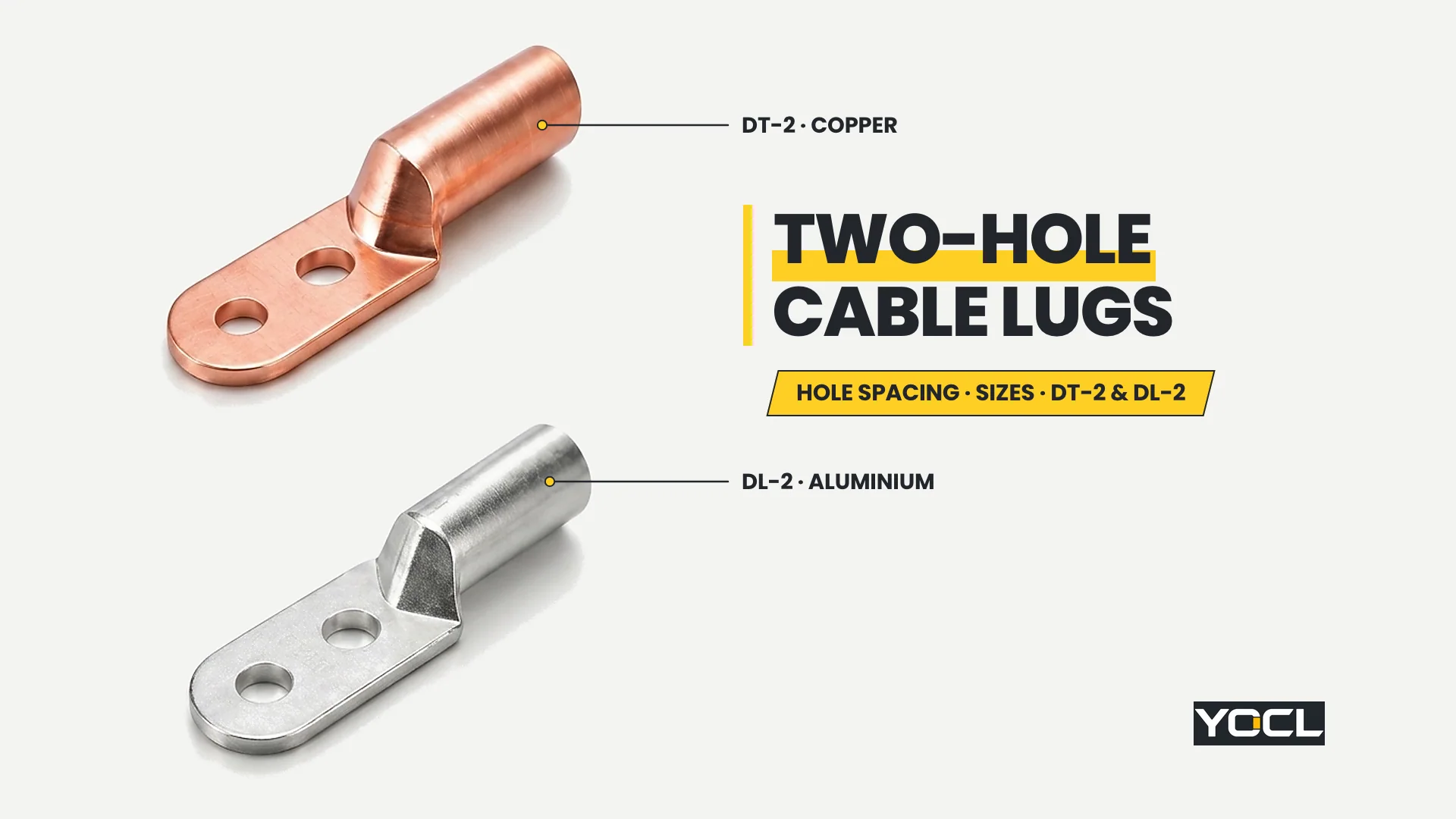
Two-hole cable lugs are compression tube terminals built with one conductor barrel and an extended flat mounting palm punched with two inline bolt holes, locking the palm’s angular orientation on two-stud equipment terminals and busbars. Across YOCL ELECTRIC’s DT-2 copper and DL-2 aluminium series, 27 models cover 16–630 mm².
Specifying a two-hole palm requires more than matching a cable cross-section and a bolt diameter. Because two bolts pass through the same rigid palm, the lug fits the equipment terminal only when both the mounting-hole diameter Φ and the centre-to-centre hole spacing L3 match the terminal’s hole pattern simultaneously. To keep neighbouring topics distinct, single-hole and general lug dimensions belong to the cable lug size chart, matching conductor and lug metals belongs to copper vs aluminium vs bimetallic cable lugs, joint preparation for aluminium barrels belongs to aluminium cable lug antioxidant compound, and compression tooling belongs to how to match cable lugs, crimp dies and conductors.
What a Two-Hole Cable Lug Is: Orientation Lock vs Single-Bolt Rotation
A two-hole cable lug combines one cylindrical conductor barrel with one elongated flat palm carrying two inline mounting holes. The second hole is not a spare attachment point: fastening two bolts along the palm centreline fixes the palm’s orientation and eliminates rotational freedom around the bolt axis.
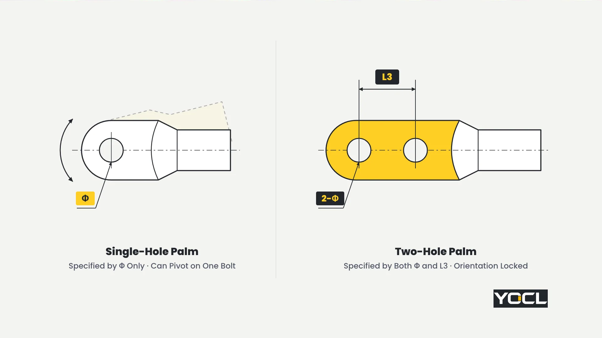
From a geometric and installation standpoint, comparing a single-bolt palm against a two-bolt palm explains why two fixing points are used on larger terminations:
- Why a single-bolt palm can rotate: A single mounting hole constrains movement across the pad face but leaves one rotational degree of freedom around the bolt shaft. Under the bending stiffness of a heavy power cable, side load during installation dressing, or a bolt that has lost clamping force, a single-bolt palm can pivot sideways around its stud.
- How two bolts remove rotational freedom: Adding a second mounting hole at centre-to-centre distance L3 establishes a two-point line constraint. With both bolts installed, the palm cannot twist toward adjacent phase bars, enclosure walls, or neighbouring lugs.
- Geometry and installation practice only: YOCL’s product pages state the structural configuration—one conductor barrel, two mounting holes, and the intended connection of a copper or aluminium conductor to an electrical equipment terminal—without publishing comparative vibration, pull-out, torque, or current data. Treat the two-hole palm strictly as an orientation-fixing and terminal-matching geometry.
The Specification Difference: Matching Both Hole Diameter (Φ) and Centre Spacing (L3)
While a single-hole lug palm is specified by a single fit dimension—its mounting-hole diameter—a two-hole lug palm is specified by two mandatory fit dimensions at once: individual hole diameter Φ and centre-to-centre hole spacing L3. Both values must match the equipment terminal’s hole pattern.
Four rules govern every two-hole lug specification:
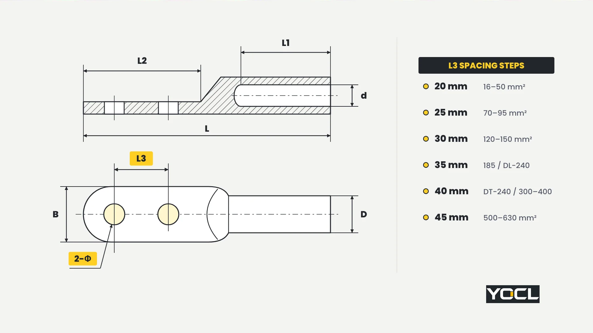
- Drawing field definitions: On both YOCL product pages, Φ is the diameter of each mounting hole, L3 is the centre-to-centre spacing of the two holes, D is the barrel outer diameter, d is the barrel inner diameter, B is the palm width, and L, L1, and L2 follow the overall, barrel, and palm length callouts on the page drawings. Every dimension is in millimetres, and the model suffix is the conductor size in mm².
- L3 steps in six discrete increments: Across both the DT-2 and DL-2 ranges, L3 is not continuous and is not fixed at one universal pitch. As conductor cross-section grows, L3 steps through 20 mm, 25 mm, 30 mm, 35 mm, 40 mm, and 45 mm.
- A 5 mm L3 mismatch does not fit at all: If a lug’s hole diameter Φ matches the terminal studs but its centre spacing L3 is even 5 mm off—such as a 35 mm spacing palm held against a 40 mm spacing busbar—the second bolt cannot enter the hole.
- Order by the terminal pattern, not by conductor size alone: A lug with the wrong L3 cannot be “made to fit” without re-drilling or slotting the palm, which modifies the lug outside the product as supplied. Always check the equipment terminal’s hole diameter and centre-to-centre spacing before ordering.
Two-Hole Cable Lugs Size Charts: YOCL DT-2 Copper and DL-2 Aluminium Series
Specifying two-hole cable lugs from YOCL ELECTRIC requires checking the exact table for your conductor material: DT-2 for copper conductors (13 models, 25–630 mm²) and DL-2 for aluminium conductors (14 models, 16–630 mm²). Never merge the two charts or use one material’s row for the other.
Table A: DT-2 Two-Hole Copper Cable Lugs (25–630 mm², 13 Models)
YOCL’s DT-2 two-hole copper cable lugs are copper compression lugs with one conductor barrel and two mounting holes, designed to connect copper conductors (25–630 mm²) to electrical equipment terminals.
Across the 13 DT-2 models, hole diameter Φ steps through 8.5, 10.5, 12.5, 14.5, 16.5, and 21 mm, while centre-to-centre spacing L3 steps through 20, 25, 30, 35, 40, and 45 mm.
| Model | Φ (mm) | D (mm) | d (mm) | L (mm) | L1 (mm) | L2 (mm) | L3 (mm) | B (mm) |
|---|---|---|---|---|---|---|---|---|
| DT-2-25 | 8.5 | 11 | 7.8 | 86 | 32 | 40 | 20 | 18 |
| DT-2-35 | 10.5 | 12 | 8.7 | 98 | 34 | 47 | 20 | 20 |
| DT-2-50 | 10.5 | 14 | 9.7 | 105 | 40 | 50 | 20 | 23 |
| DT-2-70 | 12.5 | 16 | 12 | 118 | 45 | 55 | 25 | 26 |
| DT-2-95 | 12.5 | 18 | 13.5 | 125 | 48 | 57 | 25 | 28 |
| DT-2-120 | 14.5 | 20 | 15.5 | 135 | 50 | 65 | 30 | 30 |
| DT-2-150 | 14.5 | 22 | 16.5 | 142 | 53 | 68 | 30 | 34 |
| DT-2-185 | 14.5 | 25 | 18.5 | 145 | 55 | 71 | 35 | 37 |
| DT-2-240 | 16.5 | 27 | 21 | 160 | 59 | 74 | 40 | 40 |
| DT-2-300 | 16.5 | 30 | 23 | 172 | 62 | 81 | 40 | 45 |
| DT-2-400 | 16.5 | 34 | 26 | 181 | 68 | 82 | 40 | 50 |
| DT-2-500 | 21 | 38 | 29.5 | 203 | 73 | 96 | 45 | 60 |
| DT-2-630 | 21 | 45 | 35 | 220 | 84 | 107 | 45 | 60 |
Selection Rule: Use Table A (DT-2) exclusively for copper conductors (25–630 mm²), confirming that Φ, L3, and palm width B match the equipment terminal drawing.
Table B: DL-2 Two-Hole Aluminium Cable Lugs (16–630 mm², 14 Models)
YOCL’s DL-2 two-hole aluminium cable lugs are aluminium compression lugs with one conductor barrel and two mounting holes, designed to connect aluminium conductors (16–630 mm²) to electrical equipment terminals.
The 14-model DL-2 range begins at DL-2-16 (16 mm²) and is not interchangeable with the copper table: barrel diameters D and d, lengths L / L1 / L2, and the 240 mm² and 400 mm² palm hole patterns differ from DT-2. For joint preparation on aluminium barrels, see aluminium cable lug antioxidant compound.
| Model | Φ (mm) | D (mm) | d (mm) | L (mm) | L1 (mm) | L2 (mm) | L3 (mm) | B (mm) |
|---|---|---|---|---|---|---|---|---|
| DL-2-16 | 8.5 | 10 | 5.5 | 93 | 32 | 44 | 20 | 18 |
| DL-2-25 | 8.5 | 12 | 7 | 94 | 33 | 45 | 20 | 18 |
| DL-2-35 | 10.5 | 14 | 8.5 | 104 | 42 | 48 | 20 | 20 |
| DL-2-50 | 10.5 | 16 | 9.5 | 112 | 47 | 50 | 20 | 23 |
| DL-2-70 | 12.5 | 18 | 12 | 125 | 48 | 59 | 25 | 26 |
| DL-2-95 | 12.5 | 21 | 13 | 136 | 53 | 60 | 25 | 28 |
| DL-2-120 | 14.5 | 23 | 15 | 145 | 55 | 69 | 30 | 30 |
| DL-2-150 | 14.5 | 25 | 16 | 150 | 57 | 70 | 30 | 34 |
| DL-2-185 | 14.5 | 27 | 18 | 162 | 63 | 76 | 35 | 37 |
| DL-2-240 | 14.5 | 30 | 20 | 170 | 66 | 77 | 35 | 40 |
| DL-2-300 | 16.5 | 34 | 23 | 180 | 73 | 78 | 40 | 45 |
| DL-2-400 | 21 | 38 | 26 | 195 | 76 | 87 | 40 | 50 |
| DL-2-500 | 21 | 42 | 30 | 205 | 80 | 91 | 45 | 60 |
| DL-2-630 | 21 | 45 | 34.5 | 210 | 85 | 95 | 45 | 60 |
Selection Rule: Use Table B (DL-2) exclusively for aluminium conductors (16–630 mm²), and read Φ and L3 directly from the DL-2 row rather than assuming parity with DT-2.
Reading the Charts: Selection Order and Worked Examples
To select the right model without palm-fit errors, follow a strict verification sequence: match conductor size and material to the model first, verify Φ and L3 against the equipment terminal drawing second, and check palm width B against the terminal face third.
Step-by-Step Selection Order
- Conductor size and material → Model: Pick DT-2 for a copper conductor or DL-2 for an aluminium conductor (never fit an aluminium lug on a copper cable or the reverse; see copper vs aluminium vs bimetallic cable lugs) and locate the row matching your conductor cross-section in mm².
- Verify Φ and L3 against the terminal drawing: Check that both the hole diameter Φ and the centre-to-centre hole spacing L3 in that row match the equipment terminal’s hole pattern.
- Check palm width B against the terminal face: Confirm that B (from 18 mm up to 60 mm) fits cleanly within the terminal pad width and phase barriers.
Worked Examples: 95 mm² Coincidence vs 240 mm² and 400 mm² Divergence
- 95 mm² Copper vs Aluminium (Coincidence of One Row):
A 95 mm² copper conductor terminating on a two-hole pad with 12.5 mm holes at 25 mm centres selects DT-2-95, which has Φ = 12.5 mm, L3 = 25 mm, and B = 28 mm (with D = 18 mm, d = 13.5 mm, L = 125 mm, L1 = 48 mm, L2 = 57 mm). For a 95 mm² aluminium conductor, DL-2-95 happens to share Φ = 12.5 mm, L3 = 25 mm, and B = 28 mm (while its barrel and length dimensions change to D = 21 mm, d = 13 mm, L = 136 mm, L1 = 53 mm, L2 = 60 mm). That palm match at 95 mm² is a coincidence of this row, not a cross-table rule. - 240 mm² Copper vs Aluminium (Both Φ and L3 Diverge):
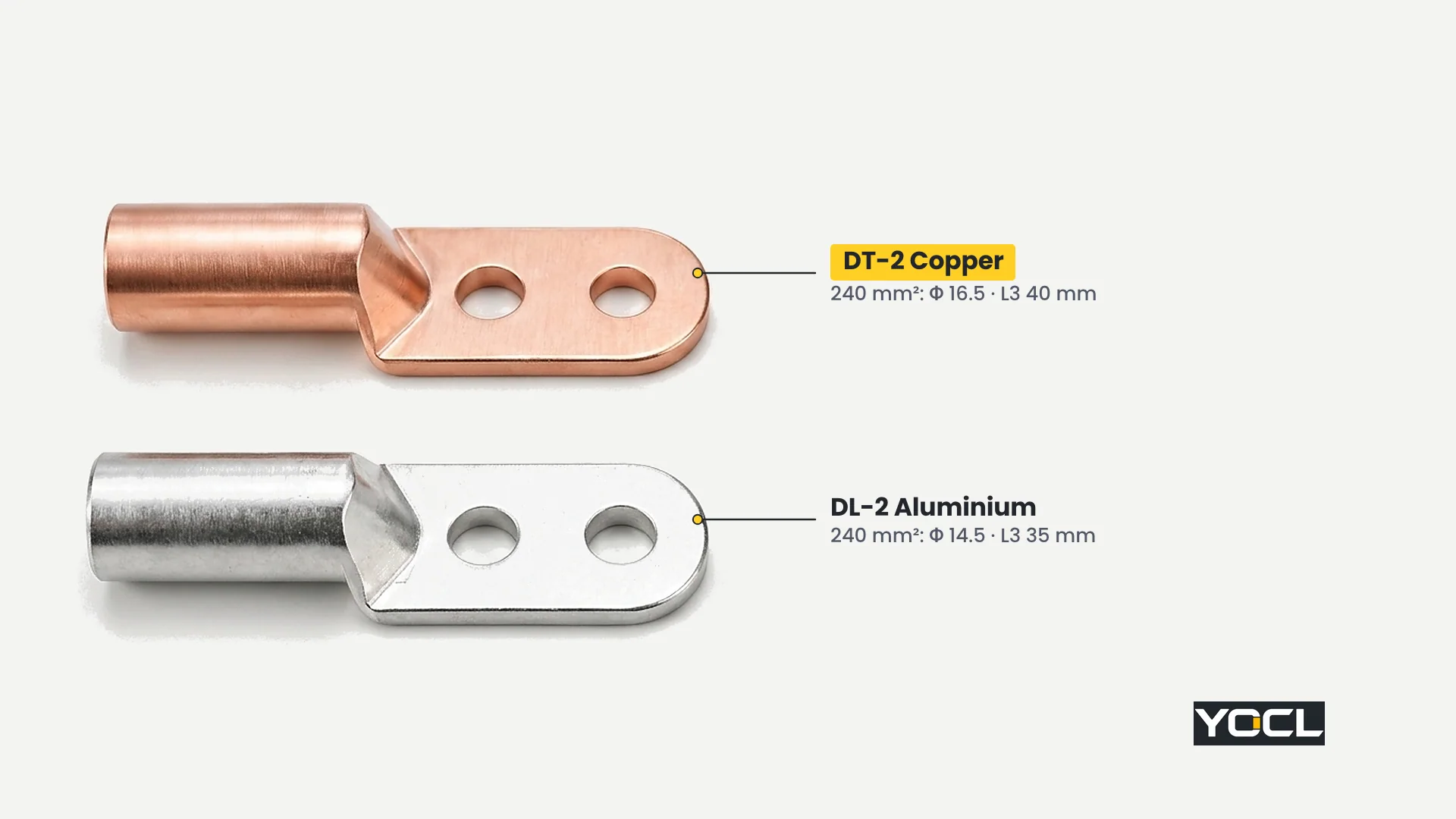
At 240 mm², the two materials diverge in both palm fit dimensions. In Table A, DT-2-240 (copper) has Φ = 16.5 mm, D = 27 mm, d = 21 mm, L = 160 mm, L1 = 59 mm, L2 = 74 mm, L3 = 40 mm, and B = 40 mm. In Table B, DL-2-240 (aluminium) has Φ = 14.5 mm, D = 30 mm, d = 20 mm, L = 170 mm, L1 = 66 mm, L2 = 77 mm, L3 = 35 mm, and B = 40 mm. A buyer terminating a 240 mm² aluminium cable must check the DL-2-240 row separately: its 14.5 mm holes at 35 mm centres will not fit a terminal drilled for 16.5 mm holes at 40 mm centres. - 400 mm² Copper vs Aluminium (Hole Diameter Φ Diverges):
At 400 mm², both rows share L3 = 40 mm and B = 50 mm, but DT-2-400 has Φ = 16.5 mm (D = 34, d = 26, L = 181, L1 = 68, L2 = 82 mm) whereas DL-2-400 has Φ = 21 mm (D = 38, d = 26, L = 195, L1 = 76, L2 = 87 mm).
When One Bolt Is Not Enough: How the Terminal and Application Decide
Answering when one bolt is not enough begins with the equipment terminal itself: the terminal as built decides first. A single-hole equipment terminal takes a single-hole lug, and no lug preference overrides the hardware pattern on the equipment.
Where termination geometry is being specified or matched on site, three rules apply:
- The equipment terminal pattern comes first: Two-hole palms belong on equipment terminals and busbar ends that provide a matching two-hole pattern (Φ and L3). Where an equipment stud or busbar pad has only one hole, specify a single-hole lug.
- Where orientation lock matters: Two-hole palms are specified where heavy feeders could twist a single-bolt palm out of alignment during installation pulling, where tight phase-to-phase spacing requires the palm to stay fixed inline with the busbar, or where the equipment manufacturer provides two inline studs to prevent palm rotation.
- Conductor size is a hint, not a current rule: YOCL’s two-hole ranges start at 25 mm² in copper (DT-2) and 16 mm² in aluminium (DL-2) and run to 630 mm², while smaller wire sizes are covered by single-hole ranges (see the cable lug size chart). Do not apply an assumed current threshold for switching to two holes—the product pages publish no current ratings for these series.
Installation Notes: Both Bolts Installed and Pre-Crimp Spacing Checks
Installing a two-hole lug requires two field habits that follow directly from the data: every two-hole palm must be fastened with both bolts, and L3 must be verified against the terminal before the barrel is crimped onto the cable.
- Both bolts belong to the joint: Fitting only one bolt of a two-hole palm into a single-hole terminal leaves the palm free to rotate around that single bolt—the exact failure mode the second hole exists to prevent—while leaving half of the palm overhanging the contact pad.
- Check L3 before crimping: Verify Φ and L3 on the terminal drawing or by measuring centre-to-centre directly on the terminal pad before crimping. After compression, a lug with the wrong hole spacing cannot be exchanged without cutting the conductor back.
- Use the matching crimp die: Match the compression die to the barrel’s series and size (D and d differ between DT-2 and DL-2); see how to match cable lugs, crimp dies and conductors.
Frequently Asked Questions
Can I use a two-hole cable lug on a terminal with only one hole?
No. Both holes of a two-hole palm belong to the joint. Fastening only one bolt of a two-hole lug onto a single-hole terminal leaves the palm free to rotate on that single bolt—the exact problem the second hole exists to prevent. Always fit a single-hole lug to a single-hole terminal.
How do I measure hole spacing on a two-hole lug?
Hole spacing L3 is measured centre-to-centre between the two mounting holes in millimetres, not edge-to-edge. Measure the centre-to-centre distance and hole diameter Φ on the equipment terminal or drawing, then match both numbers to the Φ and L3 columns in the DT-2 or DL-2 table.
Is a two-hole cable lug stronger than a single-hole lug?
YOCL’s DT-2 and DL-2 product pages publish no comparative mechanical strength, torque, vibration, or current figures. The difference is fixing geometry and terminal fit: two inline bolts separated by L3 lock the palm’s orientation so it cannot rotate around a single bolt axis.
Does the hole spacing change with lug size?
Yes. Across both the DT-2 (25–630 mm²) and DL-2 (16–630 mm²) charts, centre-to-centre hole spacing L3 steps from 20 mm to 25 mm, 30 mm, 35 mm, 40 mm, and 45 mm as conductor size increases, and differs between copper and aluminium at 240 mm² (40 mm vs 35 mm).
References
- YOCL ELECTRIC Product Information — DT-2 Two-Hole Copper Cable Lugs: copper two-hole lug specifications, drawing field definitions (Φ, D, d, L, L1, L2, L3, B), and 13-model table (25–630 mm²).
- YOCL ELECTRIC Product Information — DL-2 Two-Hole Aluminium Cable Lugs: aluminium two-hole lug specifications, drawing field definitions (Φ, D, d, L, L1, L2, L3, B), and 14-model table (16–630 mm²).