
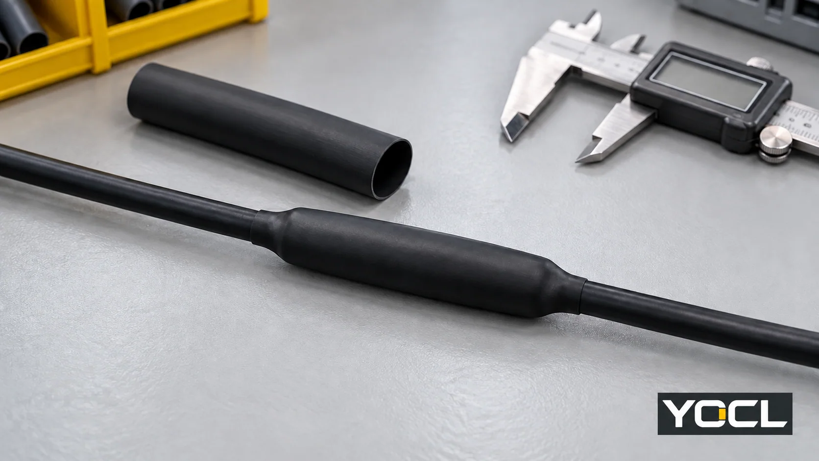
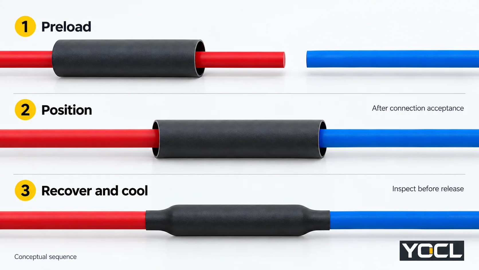
En büyük ek parçasının üzerinden geçebilen, en küçük oturma çapının altında daralan ve daralma sonrası gerekli kapsama alanını koruyan ısıyla daralan makaron seçin. Bağlantıyı kapatmadan önce kesin ve önceden yükleyin, elektriksel bağlantıyı kabul edin, makaronu konumlandırın, belirtilen ısıtma işlemiyle daraltın, ardından soğutun, inceleyin ve gerekli montaj testlerini tamamlayın.
Bu prosedür, belirtilen düz hat ek yerini kapsar. Isıyla daralan makaron belirtilen yalıtımı veya korumayı sağlar; elektriksel bağlantıyı yapmaz. Korumalı, çok damarlı ve orta veya yüksek voltajlı ek yerleri kendi montaj talimatlarına ihtiyaç duyar. Sıkıca daralmış bir makaron, bir ek yerinin elektriksel olarak kabul edilebilir veya çevresel olarak sızdırmaz olduğunun kanıtı değildir.
1. İş talimatlarını ve izolasyonu onaylayın
Kabloyu kesmeden veya ısı uygulamadan önce, ek çizimini, birleştirme talimatlarını, kesin makaron verilerini, uygulama sürecini ve kabul gereksinimlerini alın. Ekipman ve saha prosedürüne göre enerjisiz olduğu doğrulanmış izole edilmiş bir devre üzerinde çalışın. U.S. iş yerlerinde, OSHA 1910.333(b) kilitleme/etiketleme ve yetkili bir kişi tarafından doğrulama işlemlerini belirler.
Ölçümleri nihai kabul kararına bağlamak için bir iş kaydı kullanın:
| Başlamadan önce kayıt | Kontrol ettiği karar |
|---|---|
| Kablo/kılıf, ek yeri ve manşon tanımlaması | Malzeme uyumluluğu ve geçerli talimatlar |
| Manşonun yerleştirme yolundaki en büyük özellik | Gerekli sağlanan iç çap |
| Sol ve sağ iniş dış çapları | Her iki tarafta gerekli geri kazanım |
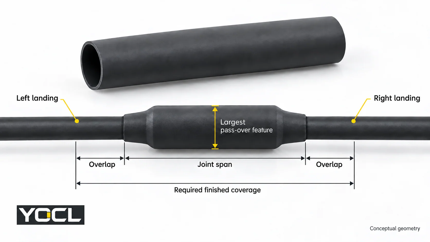
| Her iki tarafta ek yeri açıklığı ve belirtilen bindirme | Minimum bitmiş kapsama alanı |
| Elektriksel görev, ortam ve mevcut alan | Yapı, duvar ve montaj uygunluğu |
| Isıtma, soğutma ve kabul talimatları | İşlem limitleri ve serbest bırakma kontrolleri |
Uygun ölçüm aletlerine, bir kesiciye, belirtilen birleştirme aletlerine ve izin verilen kontrollü bir ısı kaynağına sahip olun. Gerekli bir talimat veya kabul kriteri eksikse işi durdurun.
2. Yapıyı seçin ve her iki çapı da kontrol edin
Belirtilen görev için yapıyı seçin. YOCL’ın ısıyla daralan makaron serisi tek cidarlı HTS makaronları ve HS3X/HS4X yapışkan astarlı makaronları içerir. Astarsız bir kılıf, yalıtım/koruma gereksinimi için kullanılabilir; yapışkan astarlı bir kılıf, sızdırmazlık gerektiğinde uyumlu bir ceket arayüzü ve doğrulanmış bir uygulama süreci gerektirir. Kullanın tek cidarlı ve çift cidarlı kılavuzu bu karar çözülmezse.
Makaronun geçmesi gereken herhangi bir konektör omzunu da içeren tam yerleştirme yolunu ölçün. İniş çaplarının her ikisini de ayrı ayrı kaydedin; iletken kesit alanı bir ceket çapı değildir. Sağlanan minimum iç çapı en büyük geçiş özelliğine karşı ve kurtarılan maksimum iç çapı en küçük inişe karşı kontrol edin.
Daha büyük önce/daha küçük sonra prensibi şurada görünür KSC-E-165 Revizyon F, §3.8.1.1.1(a), KSC yer destek kontrol ve izleme ekipmanları için bir spesifikasyondur. Bu, evrensel bir kurulum payı değil, bu boyutsal ekranı destekler.
Örneğin, bir 7.4 mm en büyük geçiş özelliği ve bir 4.0 mm en küçük iniş varsayalım. Mevcut YOCL HS3X tablosu şunu verir:
| HS3X nominal size | Supplied ID | Recovered ID | Preliminary result |
|---|---|---|---|
| 6.4 mm | ≥6.4 mm | ≤2.2 mm | Guaranteed supplied minimum does not clear 7.4 mm |
| 9.5 mm | ≥9.5 mm | ≤3.2 mm | Clears both basic diameter checks |
The 9.5 mm row is a dimensional candidate, not an approved sealed splice. Confirm the required insertion allowance, tolerances, wall/space, duty and jacket compatibility. Consult the size chart for other rows; use the shrink-ratio comparison when passage and landing geometry demand another ratio.
3. Determine cut length and preload the sleeve
Finished coverage must include the joint span and the specified overlap on each side. Allow for longitudinal change using the applicable process data. Do not substitute an arbitrary extra-length percentage or a laboratory axial-change value for an established installation allowance.
Where the instructions establish a maximum shortening fraction s, a planning calculation is:
Minimum cut length = (joint span + left overlap + right overlap) ÷ (1 − s)
Use the specified overlap and validated s for that application, round up to the permitted cut length, and verify actual coverage after cooling. If those inputs are unknown, the calculation cannot release the sleeve for cutting.
YOCL’nın HTS installation notes direct cutting to the required length and sliding tubing on before completing the connection when necessary. Preload the selected sleeve while access remains. Park it clear of the connection-making area under the joining instructions.
If access has been closed without preloading, stop for an approved correction; slitting a standard closed tube does not make it an approved wraparound sleeve.
4. Complete and accept the connection before covering it
Make the splice using its specified connector, conductor combination and joining procedure. Complete the required connection inspection before the sleeve conceals the joint. A failed or undocumented connection remains on hold even if the tubing fits.
Prepare the landing surfaces according to the selected jacket, sleeve and adhesive instructions. If they require cleaning, priming or drying, follow those material-specific directions. Do not improvise a solvent or abrasion method. For an adhesive-lined sealing job, unresolved surface compatibility or preparation means the sleeve is not ready for application.
5. Position the sleeve to the drawing
Move the sleeve into its specified position and check coverage at both ends.
Expected result: the joint and both required landing overlaps lie within the intended finished coverage. Reposition before heating if one end lacks coverage; extra material on the other end does not satisfy that requirement.
6. Recover with the specified heating process
HTS requires uniform recovery with controlled, even heat; other models need their applicable process.
Use the heat source, heating sequence, exposure limits and completion criteria established for the actual assembly. A catalogue shrink temperature is not a heat-gun dial setting, nozzle distance or dwell time. If these process requirements are unresolved, obtain the applicable instructions before heating.
NASA-STD-8739.4A Change 4, §9.9, in its NASA mission-hardware scope, ties heat and exposure to tubing size/type and requires protection of the covered item and nearby heat-sensitive parts. These are useful workmanship boundaries; they do not establish settings for a YOCL splice.
Hold the assembly if the specified recovery cannot be completed within its thermal limits or visible heat damage develops.
7. Cool and inspect the application
Let HTS cool before handling; follow the selected assembly’s cooling and inspection instructions. Check:
- Position and actual finished coverage against the drawing.
- Uniform recovery and grip where required.
- Cracks, punctures, blisters or burned areas, plus damage to the cable jacket.
- Any model-specific adhesive and interface acceptance criteria.
NASA-STD-8739.4A §§9.10–9.11 provide scoped examples of positioning, recovery/grip and visible defect checks. Appearance alone does not establish electrical performance or a complete hidden adhesive bond. An adhesive bead can be a specified local process cue; by itself it does not prove an environmental seal.
Route defects or unresolved sealing to the applicable rework process. The split-or-fail-to-seal guide explains the separate diagnosis task; do not keep reheating without authorized rework instructions.
8. Complete the release record before restoration
Record three separate decisions: connection accepted, sleeve workmanship accepted, ve required assembly tests passed. Enter the cable/splice and sleeve identification, measured coverage, process reference and test results. A missing seal-verification requirement cannot be replaced with “looks tight.”
Complete the specified electrical and, where required, environmental acceptance tests using the assembly procedure. Hold failed or incomplete results. Restore service only through the equipment/site authorization process; OSHA 1910.333(b)(2)(v) sets out restoration checks for its U.S. workplace scope.
For YOCL model selection, provide the pass-over dimension, both landing diameters, required coverage, jacket material and duty when requesting the applicable tubing and process documentation. That information turns a catalogue size candidate into a reviewable application choice.
Referanslar
- OSHA — 29 CFR 1910.333, electrical work practices, verification and restoration.
- YOCL — Heat Shrink Tubing, current product families.
- NASA KSC — KSC-E-165 Revision F, §3.8.1.1.1(a), dimensional selection.
- YOCL — HS3X 3:1 Dual-Wall Tubing, supplied/recovered size table.
- YOCL — HTS 2:1 Single-Wall Tubing, Installation Notes.
- NASA — NASA-STD-8739.4A Change 4, §§9.9–9.11, heating and workmanship.