
Use the first chart to look up calculated American Wire Gauge (AWG) conductor area. Use the second to look up YOCL’s declared metric ferrule sizes and lengths. Conversion does not approve an AWG wire for a metric model. For E-series ferrules, F is exposed metal length; L includes the collar.
AWG to mm²: calculated conductor-area chart
These values exclude insulation and are geometric references, not ferrule ratings or measurements of a particular stranded cable. Areas are calculated from the AWG progression in NIST/NBS Copper Wire Tables, section 2.2, using NIST’s exact inch-to-millimetre conversion.
| AWG size | Calculated area (mm²), rounded to 3 decimals |
|---|---|
| 28 | 0.081 |
| 26 | 0.129 |
| 24 | 0.205 |
| 22 | 0.326 |
| 20 | 0.518 |
| 18 | 0.823 |
| 16 | 1.309 |
| 14 | 2.081 |
| 12 | 3.309 |
| 10 | 5.261 |
| 8 | 8.366 |
| 7 | 10.549 |
| 6 | 13.302 |
| 5 | 16.773 |
| 4 | 21.151 |
| 3 | 26.670 |
| 2 | 33.631 |
| 1 | 42.408 |
| 1/0 | 53.475 |
| 2/0 | 67.431 |
| 3/0 | 85.029 |
| 4/0 | 107.219 |
For numerical gauge input n, the calculation is:
d = 0.127 × 92^((36 − n) / 39), with diameterdin mm.A = π × d² / 4, with areaAin mm².
Use n = 0 for 1/0, −1 for 2/0, −2 for 3/0 and −3 for 4/0. Round only the final area; tables using rounded diameters may differ.
A conversion is not a ferrule assignment
Example: 18 AWG → 0.823 mm², calculated. This is not a metric ferrule approval. Do not select a model by rounding to the nearest metric row or automatically moving up one size.
IEC 60228 defines nominal cross-sectional area as a conductor-size identifier rather than a quantity determined by direct measurement. This reinforces the distinction between a reference calculation and a declared nominal size. IEC 60228:2023 preview, clause 3.2.
For an AWG cable, confirm the exact AWG size in the ferrule’s documented wire range, together with conductor construction and the applicable tooling. The metric table below does not establish those AWG approvals.
Metric ferrule size and barrel-length chart
YOCL E-series catalogue: declared model dimensions.
| Declared conductor size (mm²) | Listed F options (mm) | Example model | Exposed barrel F (mm) | Overall L (mm) |
|---|---|---|---|---|
| 0.25 | 6, 8 | E0208 | 8 | 12.5 |
| 0.34 | 6, 8 | E0308 | 8 | 12.5 |
| 0.5 | 6, 8, 10, 12 | E0508 | 8 | 14 |
| 0.75 | 6, 8, 10, 12 | E7508 | 8 | 14.6 |
| 1 | 6, 8, 10, 12 | E1008 | 8 | 14.7 |
| 1.5 | 8, 10, 12, 18 | E1508 | 8 | 15 |
| 2.5 | 8, 10, 12, 18 | E2508 | 8 | 15.2 |
| 4 | 9, 12, 18 | E4009 | 9 | 16.5 |
| 6 | 10, 12, 18 | E6010 | 10 | 18 |
| 10 | 12, 18 | E10-12 | 12 | 21.5 |
| 16 | 12, 18 | E16-12 | 12 | 22.2 |
Read the exposed barrel and overall length separately
F spans nose to collar shoulder, excluding under-collar metal. L includes the collar. Neither is a stripping instruction.
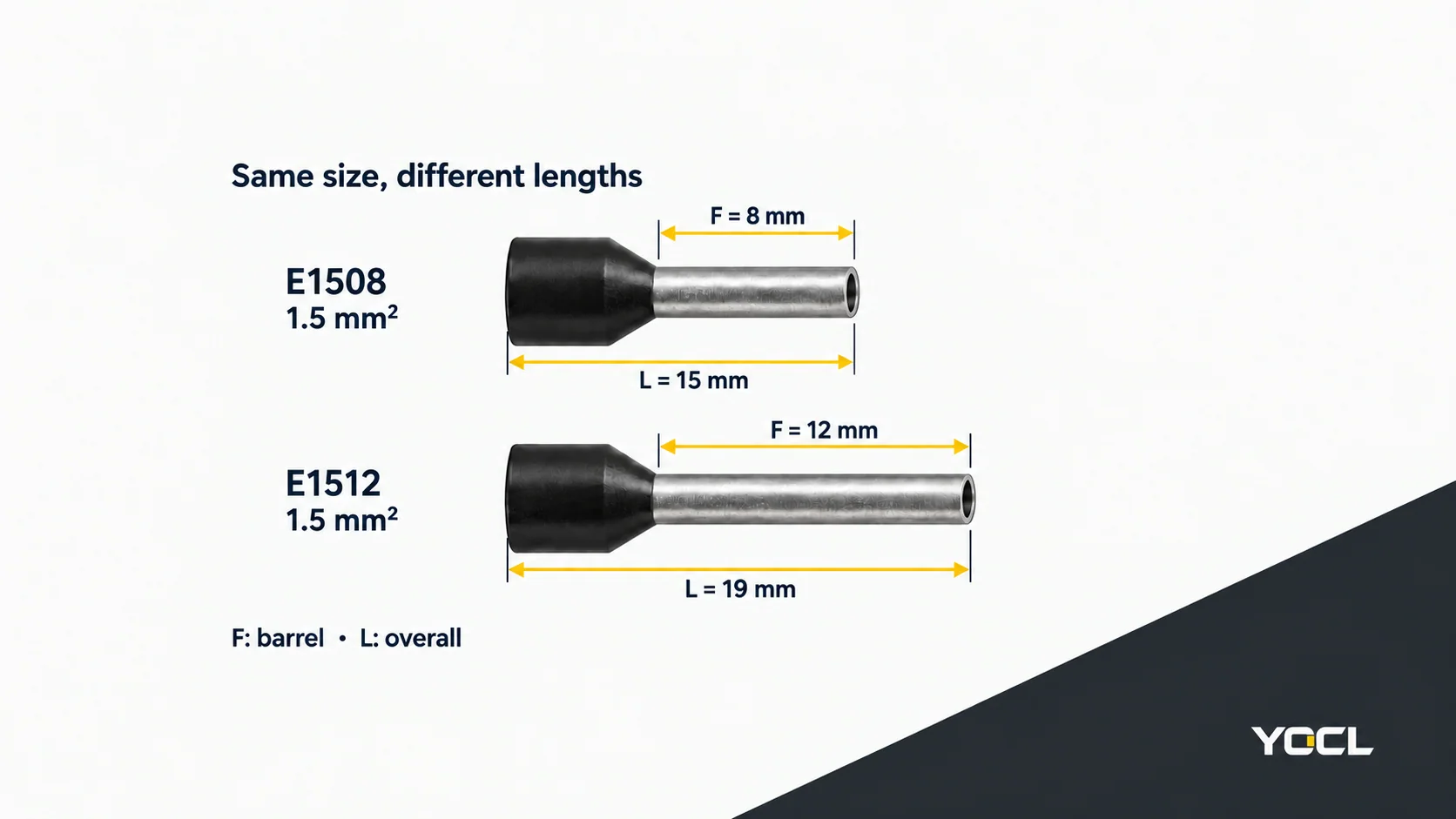
Worked lookup, 1.5 mm²: E1508 has F/L = 8/15 mm; E1512 has F/L = 12/19 mm. Check terminal documentation before choosing.
These labels follow this series drawing; check other constructions separately.
Twin ferrule notation: read the size of each wire
2 × 1.5 mm² means two conductors, each nominally 1.5 mm². Their areas add arithmetically to 3 mm², but a twin ferrule is not thereby interchangeable with a single-wire 3 mm² ferrule. Entry geometry, tooling and the receiving terminal’s permitted arrangement still need checking.
YOCL’nın TE twin ferrule catalogue declares TE 1508 as 2 × 1.5 mm², with F = 8 mm and L = 15.5 mm.
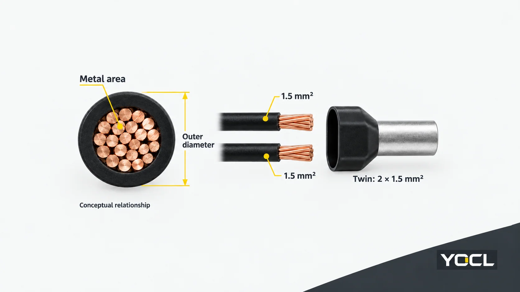
Halka açıklığı UL 486F covers ferrules for one stranded copper conductor or two stranded copper conductors of the same size. That scope explains the arrangement; it does not establish UL certification or a terminal approval for these YOCL examples. UL 486F official public scope.
Check the receiving terminal before choosing a length
Listed F options are not universal length recommendations. A size-chart row identifies dimensions; the receiving device determines the permitted prepared-conductor arrangement and length requirements.
For connectors within its scope, UL 486A-486B allows ferrules evaluated under UL 486F within their ratings and installation instructions, while retaining the connector manufacturer’s exposed-conductive-length requirements. This is a standards-scope boundary, not permission to infer stripping length from F or L. UL 486A-486B, public scope, section 1.2.
Before ordering, confirm:
- The conductor material, exact size, construction and single/twin arrangement covered by the ferrule documentation.
- The receiving terminal’s permitted ferruled-conductor range and preparation requirements.
- The required exposed metal length, overall clearance and collar fit.
- The applicable ferrule/tool combination and finished profile.
Use the full catalogue model code. Collar colour alone does not establish capacity, and code patterns are not universal across suppliers.
For construction and compatibility context, read what a wire ferrule is. To review parts, use the YOCL wire-ferrule range and send the exact wire size and count, required exposed length, receiving terminal reference and quantity.
Referanslar
- NIST/NBS — Copper Wire Tables, Handbook 100, 1966, section 2.2; AWG geometric progression used for this article’s calculations.
- NIST — SI Units – Length; exact 25.4 mm per inch conversion.
- IEC — IEC 60228:2023 preview, clause 3.2; nominal cross-sectional area. Original IEC preview hosted by iTeh; full standard not consulted.
- YOCL ürün bilgileri — E-series ferrules; declared metric dimensions and external F/L spans.
- YOCL ürün bilgileri — TE Çift Kablo Ucu Konnektörleri; per-conductor size and model dimensions.
- UL Standartlar ve Etkileşim — UL 486F: Bare and Covered Ferrules, edition 3, 2024, revised August 28, 2026; public scope only.
- UL Standartlar ve Etkileşim — UL 486A-486B: Tel Konnektörleri, edition 4, March 14, 2025; public scope only, section 1.2.