
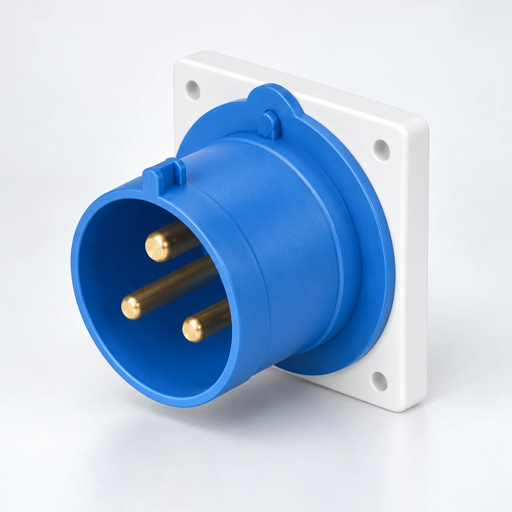
IP44 Tomadas Industriais para Aparelhos
YOCL ELECTRIC IP44 tomadas industriais em versões 16 A e 32 A. Escolha contactos 2P+E, 3P+E ou 3P+N+E, montagem em painel ou à superfície e a capacidade de condutor correspondente na tabela de modelos.
Visão Geral
As tomadas industriais YOCL ELECTRIC IP44 fornecem uma ligação de energia macho em máquinas, equipamentos de distribuição e caixas de equipamentos. A família abrange versões 16 A e 32 A em configurações 2P+E, 3P+E e 3P+N+E. As tomadas retas para painel e os designs de entrada de superfície fechados estão agrupados aqui para que a interface de alimentação possa ser selecionada juntamente com o seu arranjo de montagem. Um conector de cabo fêmea correspondente fornece a ligação de cabo destacável.
Características
- Versões IP44 para ligações industriais protegidas contra salpicos.
- Designs retos para painel em caixas padrão e K, mais designs de superfície com uma face de conector angular.
- Opções 16 A e 32 A com gamas de condutores indicadas para cada modelo.
- Posição do contacto de terra 6h nas versões listadas.
- As caixas de contacto azuis e vermelhas distinguem as configurações elétricas listadas.
Especificações Técnicas
| Parâmetro | Especificação |
|---|---|
| Marca | YOCL ELÉTRICO |
| Tipo de produto | Entrada para equipamento industrial / entrada macho para equipamento |
| Grau de proteção | IP44 |
| Opções de corrente nominal | 16 A, 32 A |
| Configurações de contacto | 2P+E; 3P+E; 3P+N+E |
| Posição do contacto de terra | 6h |
| Montagem | Montagem em painel ou montagem em superfície com caixa, dependendo do modelo |
| Interface de cabo de acoplamento | Conector de cabo industrial fêmea correspondente |
| Capacidade do condutor | Específico do modelo; ver tabela de seleção |
Seleção de Modelo
| Modelo | Montagem / caixa | Corrente (A) | Contactos | Tensão | Posição terra | Caixa do contacto | Conductor cross-section (mm²) |
|---|---|---|---|---|---|---|---|
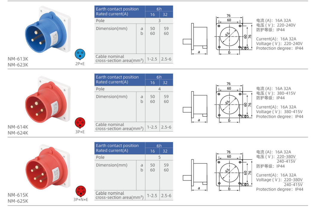
| NM-613K | Straight panel inlet, K housing | 16 | 2P+E | 220–240 V | 6h | Azul | 1–2.5 |
| NM-623K | Straight panel inlet, K housing | 32 | 2P+E | 220–240 V | 6h | Azul | 2.5–6 |
| NM-614K | Straight panel inlet, K housing | 16 | 3P+E | 380–415 V | 6h | Vermelho | 1–2.5 |
| NM-624K | Straight panel inlet, K housing | 32 | 3P+E | 380–415 V | 6h | Vermelho | 2.5–6 |
| NM-615K | Straight panel inlet, K housing | 16 | 3P+N+E | 220–380 V / 240–415 V | 6h | Vermelho | 1–2.5 |
| NM-625K | Straight panel inlet, K housing | 32 | 3P+N+E | 220–380 V / 240–415 V | 6h | Vermelho | 2.5–6 |
| NM-613 | Straight panel inlet | 16 | 2P+E | 220–240 V | 6h | Azul | 1–2.5 |
| NM-623 | Straight panel inlet | 32 | 2P+E | 220–240 V | 6h | Azul | 2.5–6 |
| NM-614 | Straight panel inlet | 16 | 3P+E | 380–415 V | 6h | Vermelho | 1–2.5 |
| NM-624 | Straight panel inlet | 32 | 3P+E | 380–415 V | 6h | Vermelho | 2.5–6 |
| NM-615 | Straight panel inlet | 16 | 3P+N+E | 220–380 V / 240–415 V | 6h | Vermelho | 1–2.5 |
| NM-625 | Straight panel inlet | 32 | 3P+N+E | 220–380 V / 240–415 V | 6h | Vermelho | 2.5–6 |
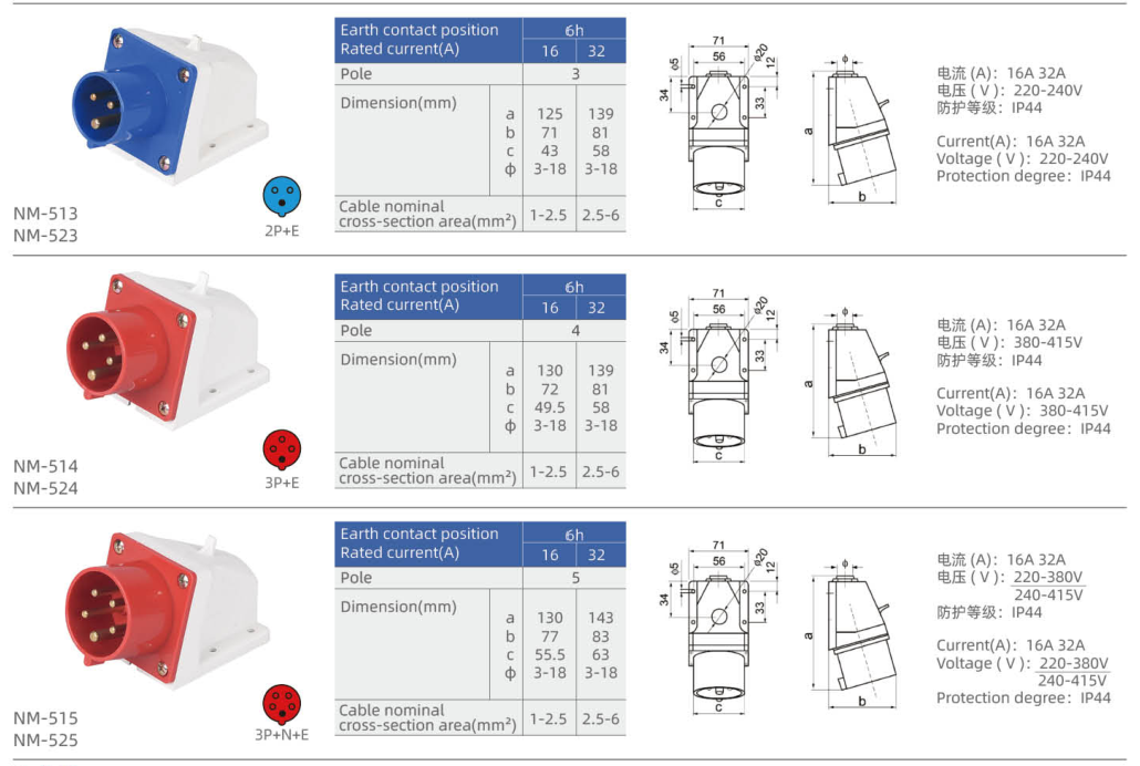
| NM-513 | Surface inlet with angled face | 16 | 2P+E | 220–240 V | 6h | Azul | 1–2.5 |
| NM-523 | Surface inlet with angled face | 32 | 2P+E | 220–240 V | 6h | Azul | 2.5–6 |
| NM-514 | Surface inlet with angled face | 16 | 3P+E | 380–415 V | 6h | Vermelho | 1–2.5 |
| NM-524 | Surface inlet with angled face | 32 | 3P+E | 380–415 V | 6h | Vermelho | 2.5–6 |
| NM-515 | Surface inlet with angled face | 16 | 3P+N+E | 220–380 V / 240–415 V | 6h | Vermelho | 1–2.5 |
| NM-525 | Surface inlet with angled face | 32 | 3P+N+E | 220–380 V / 240–415 V | 6h | Vermelho | 2.5–6 |
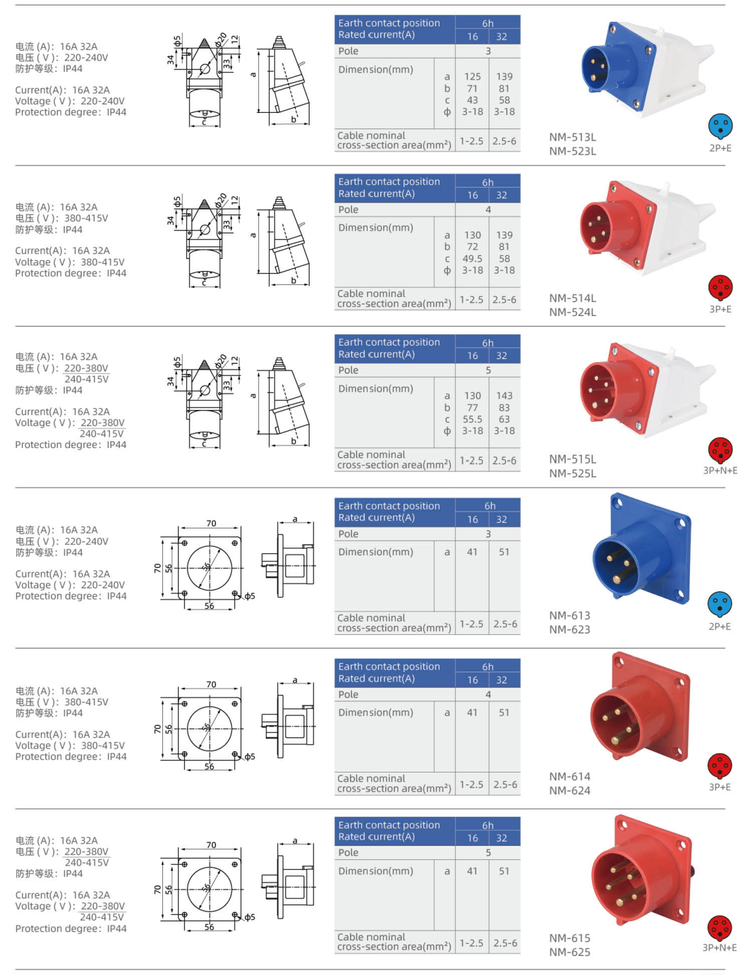
| NM-513L | Surface inlet with angled face — L housing | 16 | 2P+E | 220–240 V | 6h | Azul | 1–2.5 |
| NM-523L | Surface inlet with angled face — L housing | 32 | 2P+E | 220–240 V | 6h | Azul | 2.5–6 |
| NM-514L | Surface inlet with angled face — L housing | 16 | 3P+E | 380–415 V | 6h | Vermelho | 1–2.5 |
| NM-524L | Surface inlet with angled face — L housing | 32 | 3P+E | 380–415 V | 6h | Vermelho | 2.5–6 |
| NM-515L | Surface inlet with angled face — L housing | 16 | 3P+N+E | 220–380 V / 240–415 V | 6h | Vermelho | 1–2.5 |
| NM-525L | Surface inlet with angled face — L housing | 32 | 3P+N+E | 220–380 V / 240–415 V | 6h | Vermelho | 2.5–6 |
P denotes a phase contact, N neutral and E protective earth. A dash means that no voltage is assigned in this selection table.
Dimensão
| Modelo | Lettered outline dimensions (mm) | Fixed mounting geometry |
|---|---|---|
| NM-613K | a=50, b=60 | Flange width × height (mm): 76 × 76; Fixing centres (mm): 60 × 60; Panel opening diameter (mm): 65; Fixing hole diameter (mm): 5 |
| NM-623K | a=59, b=60 | Flange width × height (mm): 76 × 76; Fixing centres (mm): 60 × 60; Panel opening diameter (mm): 65; Fixing hole diameter (mm): 5 |
| NM-614K | a=50, b=60 | Flange width × height (mm): 76 × 76; Fixing centres (mm): 60 × 60; Panel opening diameter (mm): 65; Fixing hole diameter (mm): 5 |
| NM-624K | a=59, b=60 | Flange width × height (mm): 76 × 76; Fixing centres (mm): 60 × 60; Panel opening diameter (mm): 65; Fixing hole diameter (mm): 5 |
| NM-615K | a=50, b=60 | Flange width × height (mm): 76 × 76; Fixing centres (mm): 60 × 60; Panel opening diameter (mm): 65; Fixing hole diameter (mm): 5 |
| NM-625K | a=59, b=60 | Flange width × height (mm): 76 × 76; Fixing centres (mm): 60 × 60; Panel opening diameter (mm): 65; Fixing hole diameter (mm): 5 |
| NM-613 | a=41 | Flange width × height (mm): 70 × 70; Fixing centres (mm): 56 × 56; Panel opening diameter (mm): 46; Fixing hole diameter (mm): 5 |
| NM-623 | a=51 | Flange width × height (mm): 70 × 70; Fixing centres (mm): 56 × 56; Panel opening diameter (mm): 46; Fixing hole diameter (mm): 5 |
| NM-614 | a=41 | Flange width × height (mm): 70 × 70; Fixing centres (mm): 56 × 56; Panel opening diameter (mm): 46; Fixing hole diameter (mm): 5 |
| NM-624 | a=51 | Flange width × height (mm): 70 × 70; Fixing centres (mm): 56 × 56; Panel opening diameter (mm): 46; Fixing hole diameter (mm): 5 |
| NM-615 | a=41 | Flange width × height (mm): 70 × 70; Fixing centres (mm): 56 × 56; Panel opening diameter (mm): 46; Fixing hole diameter (mm): 5 |
| NM-625 | a=51 | Flange width × height (mm): 70 × 70; Fixing centres (mm): 56 × 56; Panel opening diameter (mm): 46; Fixing hole diameter (mm): 5 |
| NM-513 | a=125, b=71, c=43, Φ=3–18 | — |
| NM-523 | a=139, b=81, c=58, Φ=3–18 | — |
| NM-514 | a=130, b=72, c=49.5, Φ=3–18 | — |
| NM-524 | a=139, b=81, c=58, Φ=3–18 | — |
| NM-515 | a=130, b=77, c=55.5, Φ=3–18 | — |
| NM-525 | a=143, b=83, c=63, Φ=3–18 | — |
| NM-513L | a=125, b=71, c=43, Φ=3–18 | — |
| NM-523L | a=139, b=81, c=58, Φ=3–18 | — |
| NM-514L | a=130, b=72, c=49.5, Φ=3–18 | — |
| NM-524L | a=139, b=81, c=58, Φ=3–18 | — |
| NM-515L | a=130, b=77, c=55.5, Φ=3–18 | — |
| NM-525L | a=143, b=83, c=63, Φ=3–18 | — |
Use the lettered dimensions with the matching inlet outline. Flange geometry and housing size differ between body versions; select the complete model code when checking installation space.
Seleção de Ligação
Match rated current, contact configuration, voltage and earth-contact position at both sides of the connection. Select panel or surface mounting before comparing the housing dimensions. The IP rating applies to the correctly assembled connection with its compatible mating interface; maintain the specified sealing and closure arrangement.
Informações de Encomenda
Send YOCL ELECTRIC the full model code, required quantity, supply voltage, contact configuration and installation arrangement. Include conductor cross-section and the mating cable connector when requesting a complete equipment power connection.