
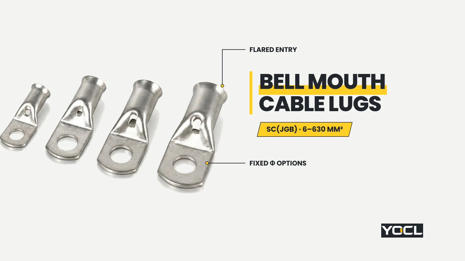
Terminais de cabos com boca de sino são terminais tubulares de compressão de cobre formados com uma abertura em forma de funil, alargada na parte traseira do corpo do condutor, para recolher e guiar os fios de cobre multifilares de forma limpa para o interior. Na série SC(JGB) da YOCL ELECTRIC, os modelos 16 cobrem condutores de 6–630 mm².
A maioria das especificações de terminais de cabos foca-se no furo do parafuso da pala e no furo do corpo, tratando a boca traseira do corpo como um corte quadrado simples. No entanto, em cabos multifilares, a borda de entrada decide se cada fio de cobre entra na zona de crimpagem ou se prende na borda durante a montagem. Para manter os tópicos vizinhos distintos, o procedimento de crimpagem (comprimento da decapagem, profundidade de inserção, colocação da crimpagem e verificações pós-crimpagem) pertence a como crimpar terminais de cabos, a seleção de ferramentas pertence a como combinar terminais de cabo, matrizes de crimpagem e condutores, e o dimensionamento geral do furo para o condutor pertence a a tabela de tamanhos de terminais de cabo. As famílias de terminais com janela de inspeção ou orifício de inspeção — tais como a YOCL’s SC(JGK) e a série JM/JGY — destinam-se à verificação visual da profundidade e não à geometria de entrada do condutor, sendo uma característica distinta do corpo do terminal.
O problema da inserção de condutores entrançados numa entrada de terminal reta
Um condutor de cobre entrançado comporta-se como um feixe elástico de fios individuais e não como uma haste rígida. Quando empurrado contra uma entrada de terminal com corte reto de 90 graus, os fios exteriores prendem-se facilmente no rebordo do terminal, espalham-se para fora ou dobram-se ao longo da parede exterior em vez de entrarem no orifício.
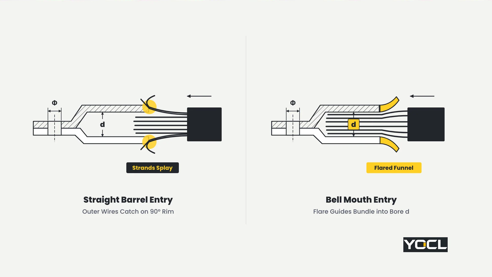
Na oficina ou dentro de um quadro elétrico, o bloqueio de fios numa entrada de terminal reta cria dois defeitos mecânicos imediatos antes mesmo de a ferramenta de cravação tocar no terminal:
- Fios presos fora do terminal: Uma vez removido o isolamento de um cabo entrançado, a camada exterior de fios relaxa ligeiramente para fora. Se o diâmetro interior do terminal d é ajustado de perto ao feixe de condutores, mesmo uma ligeira entrada em ângulo contra uma extremidade de corte quadrado prende um ou mais fios exteriores. Esses fios que escapam dobram-se para fora da parede do terminal — reduzindo a secção transversal do condutor capturada dentro da união e deixando filamentos de cobre expostos que podem desviar-se para terminais de fase adjacentes ou estruturas metálicas ligadas à terra.
- Profundidade de inserção incompleta: Mesmo quando um fio preso não se dobra totalmente para o exterior do tubo, o amontoamento na extremidade do terminal prende o feixe e impede que o condutor atinja a profundidade total de assentamento dentro do terminal.
- Porque é que as secções transversais maiores oferecem maior resistência: Em 6 mm², um fio de cobre de baixa torção é fácil de torcer entre dois dedos e inserir num tubo reto. A partir de 95 mm² e acima — através de 185 mm², 300 mm², e 630 mm²—a rigidez dos cabos pesados, os raios de curvatura apertados nos invólucros e o maior número de fios tornam o alinhamento coaxial perfeito muito mais difícil de manter manualmente, pelo que as extremidades quadradas dos terminais prendem os fios com muito mais facilidade durante a montagem.
O que a entrada do terminal alargada altera — e o que não altera
Uma boca de sino é um funil cónico suave formado na extremidade de entrada do terminal de cobre: como refere a especificação do produto YOCL’s SC(JGB), a abertura alargada ajuda a guiar os condutores — incluindo condutores de cobre entrançados — para dentro do terminal. A jusante desse rebordo de entrada, a estrutura da união mecânica e elétrica do terminal permanece inalterada.

Separar o que o alargamento altera do que permanece idêntico evita interpretações excessivas da geometria do catálogo:
- O que o alargamento altera (entrada de montagem): Em vez de apresentar um rebordo anelar plano à extremidade do fio descarnado, a boca alargada alarga a abertura alvo e afunila suavemente para dentro em direção ao orifício cilíndrico. Os fios exteriores ligeiramente soltos contactam uma rampa inclinada que reúne o conjunto de fios e guia o feixe coaxialmente para dentro do tubo.
- O que permanece idêntico a jusante: Para além do afunilamento de entrada curto, o diâmetro interno do corpo cilíndrico (d na tabela abaixo), o diâmetro externo do corpo (D), a zona de cravação por compressão, a seleção da matriz e a patilha de montagem plana de um orifício funcionam exatamente da mesma forma que nos terminais de entrada reta padrão da YOCL. SC(JGA) terminais de cobre.
- Uma funcionalidade de inserção, nunca uma melhoria elétrica: A YOCL não publica qualquer classificação de corrente, valor de tração ou classificação de temperatura para a série SC(JGB, e a boca afunilada nunca deve ser considerada como tendo maior capacidade de corrente, menor resistência de contacto ou temperaturas de funcionamento mais baixas. A qualidade da união elétrica provém do ajuste correto entre o condutor e o diâmetro interno e da compressão a frio do corpo — a boca em sino serve simplesmente para garantir que todos os fios entram efetivamente nesse corpo antes da cravação.
Tabela de tamanhos de terminais de cabo com boca em sino: YOCL Série SC(JGB (6–630 mm²)
Especificação terminais de cabo com entrada em funil em YOCL ELECTRIC SC(JGB) terminais de cabo de cobre com entrada em funil a gama abrange modelos de cobre 16 a partir de SC(JGB)-6 para SC(JGB)-630, where each model suffix identifies nominal copper conductor cross-section in mm² and every dimensional column is given in millimetres.
Understanding the Mounting-Hole Φ-Range Rule Before Ordering
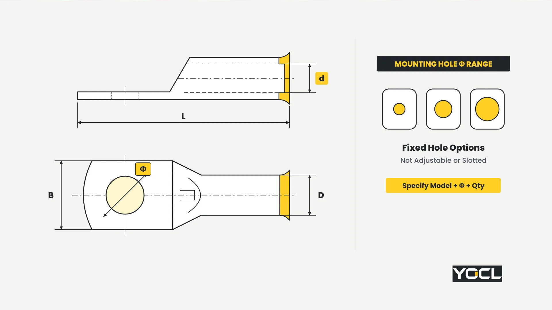
Look carefully at the Mounting-Hole Φ Range (mm) column in the SC(JGB) table below. Each row prints a millimetre range—such as 6.4–8.4 mm on SC(JGB)-6 ou 10.5–18.5 mm on SC(JGB)-240—because each conductor model is manufactured in multiple fixed stud-hole diameters within that span.
As stated on YOCL’s SC(JGB) product page, that range represents the available hole sizes for the model, not an adjustable, slotted, or one-size-fits-all hole. Every supplied lug has a single round mounting hole punched to one specific diameter. When requesting a quotation or placing an order, specify three items together:
- Complete model code (for example, SC(JGB)-95 ou SC(JGB)-240);
- Required mounting-hole diameter (chosen from that model’s published Φ range to match your equipment bolt or stud);
- Order quantity.
Complete YOCL SC(JGB) Dimensional Specification Table (16 Models)
| Modelo | Mounting-Hole Φ Range — Available Hole Sizes (mm) | D Barrel Outer (mm) | d Barrel Inner (mm) | L Overall (mm) | B Palm Width (mm) |
|---|---|---|---|---|---|
| SC(JGB)-6 | 6.4–8.4 | 5.5 | 4.5 | 23 | 10 |
| SC(JGB)-10 | 6.4–8.4 | 6.5 | 5.5 | 27 | 11 |
| SC(JGB)-16 | 6.4–12.5 | 8 | 6.6 | 33 | 12 |
| SC(JGB)-25 | 6.4–12.5 | 9 | 7.2 | 36 | 14 |
| SC(JGB)-35 | 6.4–12.5 | 10.5 | 8.7 | 42 | 16 |
| SC(JGB)-50 | 8.4–12.5 | 12 | 10 | 49 | 18 |
| SC(JGB)-70 | 8.4–12.5 | 14.5 | 12.1 | 55 | 21 |
| SC(JGB)-95 | 8.4–16.5 | 16 | 13.2 | 59 | 24 |
| SC(JGB)-120 | 10.5–16.5 | 19 | 15.6 | 67 | 29 |
| SC(JGB)-150 | 10.5–16.5 | 20.5 | 16.9 | 72 | 30 |
| SC(JGB)-185 | 10.5–16.5 | 23.5 | 19.5 | 78 | 34 |
| SC(JGB)-240 | 10.5–18.5 | 26 | 21.4 | 90 | 38 |
| SC(JGB)-300 | 10.5–18.5 | 30 | 24.4 | 100 | 42 |
| SC(JGB)-400 | 10.5–20.5 | 34 | 28.2 | 113 | 48 |
| SC(JGB)-500 | 12.5–22.5 | 38 | 32 | 126 | 54 |
| SC(JGB)-630 | 12.5–22.5 | 45 | 37.8 | 145 | 65 |
Regra de Seleção: Match nominal copper conductor cross-section to the SC(JGB) model suffix first, verify stripped conductor clearance against barrel inner diameter d (de 4.5 mm at 6 mm² up to 37.8 mm at 630 mm²), specify the exact fixed mounting-hole diameter from the row’s Φ range for your terminal bolt, and check overall length L (23–145 mm) and palm width B (10–65 mm) against terminal compartment barriers. For the general bore-and-stud sizing method across lug families, see a tabela de tamanhos de terminais de cabo.
For example, terminating a 95 mm² stranded copper feeder selects SC(JGB)-95 (d = 13.2 mm, D = 16 mm, L = 59 mm, B = 24 mm), and the buyer specifies the exact required bolt-hole diameter within 8.4–16.5 mm at order time; stepping up to a 240 mm² feeder selects SC(JGB)-240 (d = 21.4 mm, D = 26 mm, L = 90 mm, B = 38 mm) with its fixed hole chosen within 10.5–18.5 mm.
When Bell Mouth Lugs Earn Their Place — and When Straight Entry Is Fine
Flared-entry lugs are the practical answer to a specific wire-insertion problem rather than an automatic replacement for every straight-entry lug on a bill of materials. Matching the barrel mouth to conductor construction and assembly workflow keeps selection grounded:
- Where bell mouth lugs earn their place:
- Stranded and flexible multi-wire copper conductors: The higher the wire count and the finer the individual copper strands, the more readily the stripped end mushrooms or catches on a square tube edge.
- Larger cable cross-sections: On heavy feeders—such as 95 mm² (d = 13.2 mm), 185 mm² (d = 19.5 mm), 300 mm² (d = 24.4 mm), and 630 mm² (d = 37.8 mm)—guiding a stiff cable end onto a lug inside a tight termination box benefits directly from a funnelled entry.
- Repetitive panel and harness production: When an assembly line terminates hundreds of cable ends per shift, every snagged strand forces the operator to pull the cable out, re-lay the wires, and repeat the insertion. A flared entry cuts down that repetitive assembly rework.
- When a standard straight entry is completely adequate:
- Solid copper conductors: A single solid wire has no individual strands to splay or fold back at the mouth.
- Small stranded conductors that seat cleanly: On compact sizes such as 6 mm² ou 10 mm² where a neatly stripped conductor slips straight into bore d without catching, a standard straight-entry lug performs the termination without difficulty.
- Undisturbed bench terminations verified by trial fit: If the stripped conductor will not be bent or handled roughly between stripping and crimping, and a dry trial fit confirms the wire bundle enters the barrel cleanly to full depth, barrel entry geometry is not your bottleneck.
Insertion Practice with a Flared Barrel Entry
A flared mouth guides strands inward, but it does not excuse careless wire preparation or blind crimping. Follow three assembly habits whenever terminating stranded copper conductors into an SC(JGB) lug:
- Re-twist the strand lay by hand after stripping: Pulling off tough cable insulation often untwists or ruffles the outer copper layer. Before presenting the wire to the lug, gently twist the stripped strands in the natural direction of their lay so the bundle enters the bell mouth as a single coherent cylinder.
- Seat the conductor fully home before compressing: Push the cable smoothly through the flare until the conductor reaches full insertion depth inside the barrel; for strip-length matching, seating depth criteria, and crimp placement along the barrel, follow como crimpar terminais de cabos.
- Inspect the bell mouth rim before closing the crimping tool: Pause and look all the way around the flared entry lip before applying pressure. Zero strands may sit outside the flare. Any wire resting outside the bell mouth is outside the crimp barrel—closing the die over it locks a reduced-section joint and a loose external copper whisker permanently in place. If even one strand escapes, withdraw the cable, re-form the lay, and insert again before crimping.
Frequently Asked Questions
Does a bell mouth cable lug carry more current than a standard lug?
No. YOCL publishes no current rating, tensile figure, or temperature rating for the SC(JGB) series, and the flared mouth provides no ampacity, resistance, or thermal advantage over a straight-entry lug. Electrical joint quality is determined by proper bore fit (d) and barrel compression, which match standard copper tube lugs in form.
Is the mounting hole on an SC(JGB) lug adjustable?
No. The Mounting-Hole Φ Range in the SC(JGB) chart (6.4–8.4 mm through 12.5–22.5 mm) lists the range of fixed circular hole diameters manufactured for each model—never a slotted or adjustable hole. Specify the model code, the exact required mounting-hole diameter, and quantity when ordering.
Do I need different crimp dies for bell mouth cable lugs?
The crimp is made on the cylindrical barrel body downstream of the flared mouth, just as on straight-entry copper cable lugs (D das 5.5 mm para 45 mm e d das 4.5 mm para 37.8 mm across 6–630 mm²). Do not assume a special bell-mouth die; follow como combinar terminais de cabo, matrizes de crimpagem e condutores.
Should I choose a bell mouth lug or a peephole lug?
They solve two different assembly tasks. A bell mouth lug (SC(JGB)) flares the rear barrel entry to guide multi-wire stranded conductors smoothly into the bore without splaying strands, whereas a peephole lug (such as YOCL’s SC(JGK ou JM/JGY series) provides an inspection hole to check conductor seating depth before crimping.
Referências
- YOCL ELECTRIC Product Information — SC(JGB) Anilhas de Cobre para Cabos com Boca de Sino: flared-entry copper lug specifications, mounting-hole Φ-range ordering rules, and 16-model dimensional table (6–630 mm²).
- YOCL ELECTRIC Product Information — SC(JGA) Anilhas de Cobre para Cabos: standard straight-entry copper tube cable lug counterpart series (6–630 mm²).