
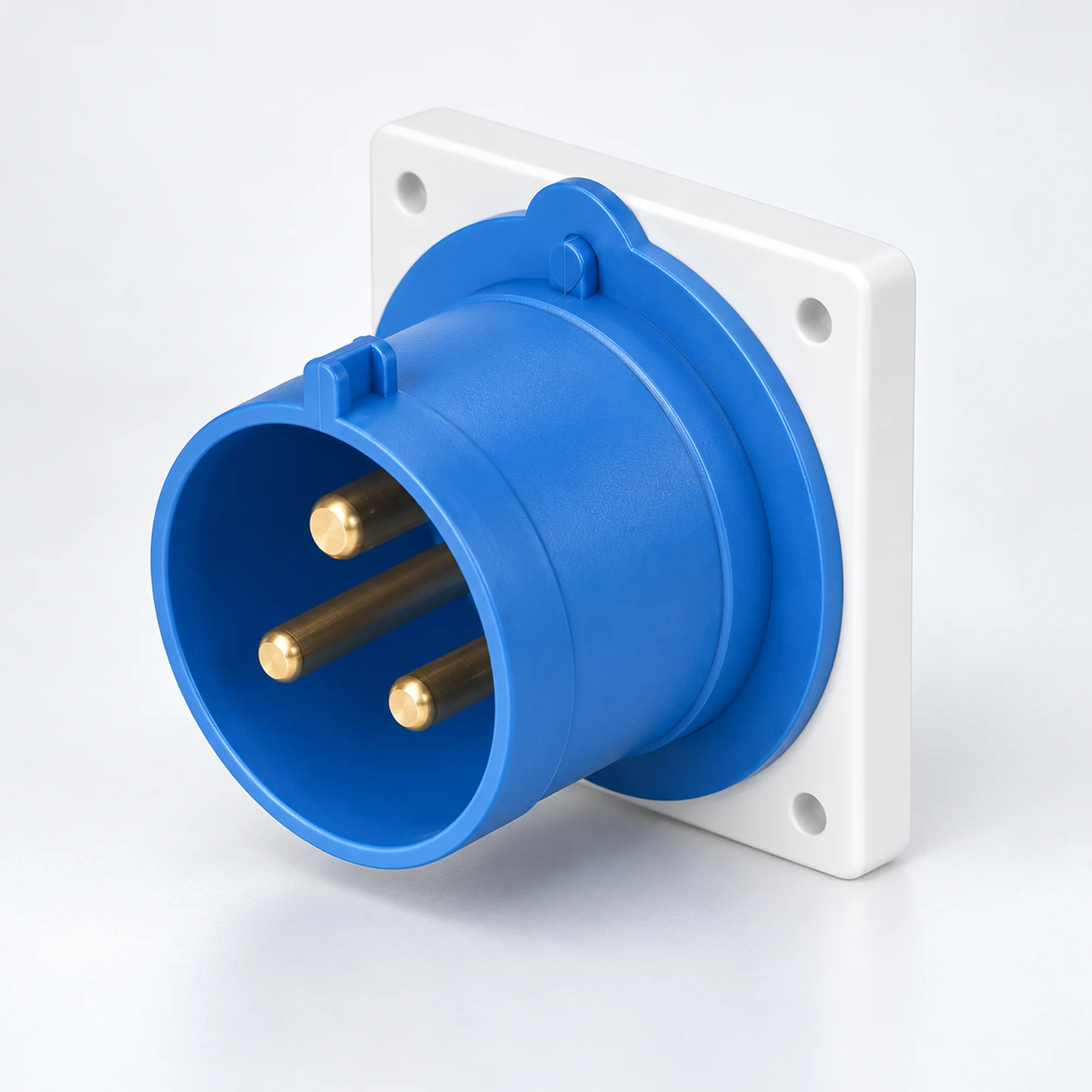
IP44 Endüstriyel Cihaz Girişleri
YOCL ELEKTRİK IP44 endüstriyel cihaz girişleri 16 A ve 32 A versiyonlarında mevcuttur. Model tablosundan 2P+E, 3P+E veya 3P+N+E kontakları, panel veya yüzeye montajı ve uygun iletken kapasitesini seçin.
Genel Bakış
YOCL ELEKTRİK IP44 endüstriyel cihaz girişleri, makineler, dağıtım ekipmanları ve ekipman muhafazalarında erkek güç bağlantısı sağlar. Bu seri, 16 A ve 32 A versiyonlarını 2P+E, 3P+E ve 3P+N+E konfigürasyonlarında kapsar. Düz panel girişleri ve kapalı yüzey giriş tasarımları burada gruplandırılmıştır, böylece besleme arayüzü montaj düzenlemesiyle birlikte seçilebilir. Uygun bir dişi kablo konektörü, ayrılabilir kablo bağlantısını sağlar.
Özellikler
- Sıçramaya karşı korumalı endüstriyel bağlantılar için IP44 versiyonları.
- Standart ve K gövdeli düz panel tasarımları ve açılı konektör yüzeyli yüzey tasarımları.
- Her model için belirtilen iletken aralıklarına sahip 16 A ve 32 A seçenekleri.
- Listelenen modellerde 6h toprak kontak konumu.
- Mavi ve kırmızı kontak yuvaları, listelenen elektriksel konfigürasyonları ayırt eder.
Teknik Özellikler
| Parametre | Teknik Özellikler |
|---|---|
| Marka | YOCL ELEKTRİK |
| Ürün tipi | Endüstriyel cihaz girişi / erkek ekipman girişi |
| Koruma derecesi | IP44 |
| Anma akımı seçenekleri | 16 A, 32 A |
| Kontak konfigürasyonları | 2P+E; 3P+E; 3P+N+E |
| Toprak teması konumu | 6h |
| Montaj | Modele bağlı olarak panel montajı veya kapalı yüzey montajı |
| Eşleşen kablo arayüzü | Eşleşen dişi endüstriyel kablo konektörü |
| İletken kapasitesi | Modele özel; seçim tablosuna bakınız |
Model Seçimi
| Model | Montaj / muhafaza | Akım (A) | Kontaklar | Voltaj | Toprak konumu | Kontak yuvası | Conductor cross-section (mm²) |
|---|---|---|---|---|---|---|---|
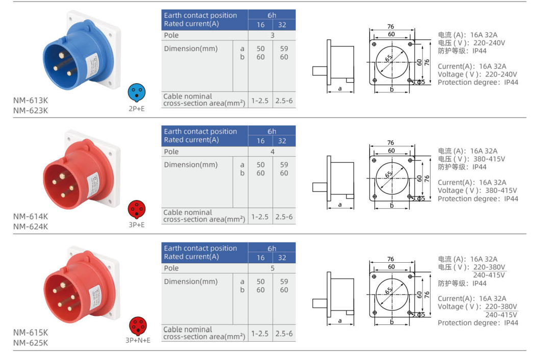
| NM-613K | Straight panel inlet, K housing | 16 | 2P+E | 220–240 V | 6h | Mavi | 1–2.5 |
| NM-623K | Straight panel inlet, K housing | 32 | 2P+E | 220–240 V | 6h | Mavi | 2.5–6 |
| NM-614K | Straight panel inlet, K housing | 16 | 3P+E | 380–415 V | 6h | Kırmızı | 1–2.5 |
| NM-624K | Straight panel inlet, K housing | 32 | 3P+E | 380–415 V | 6h | Kırmızı | 2.5–6 |
| NM-615K | Straight panel inlet, K housing | 16 | 3P+N+E | 220–380 V / 240–415 V | 6h | Kırmızı | 1–2.5 |
| NM-625K | Straight panel inlet, K housing | 32 | 3P+N+E | 220–380 V / 240–415 V | 6h | Kırmızı | 2.5–6 |
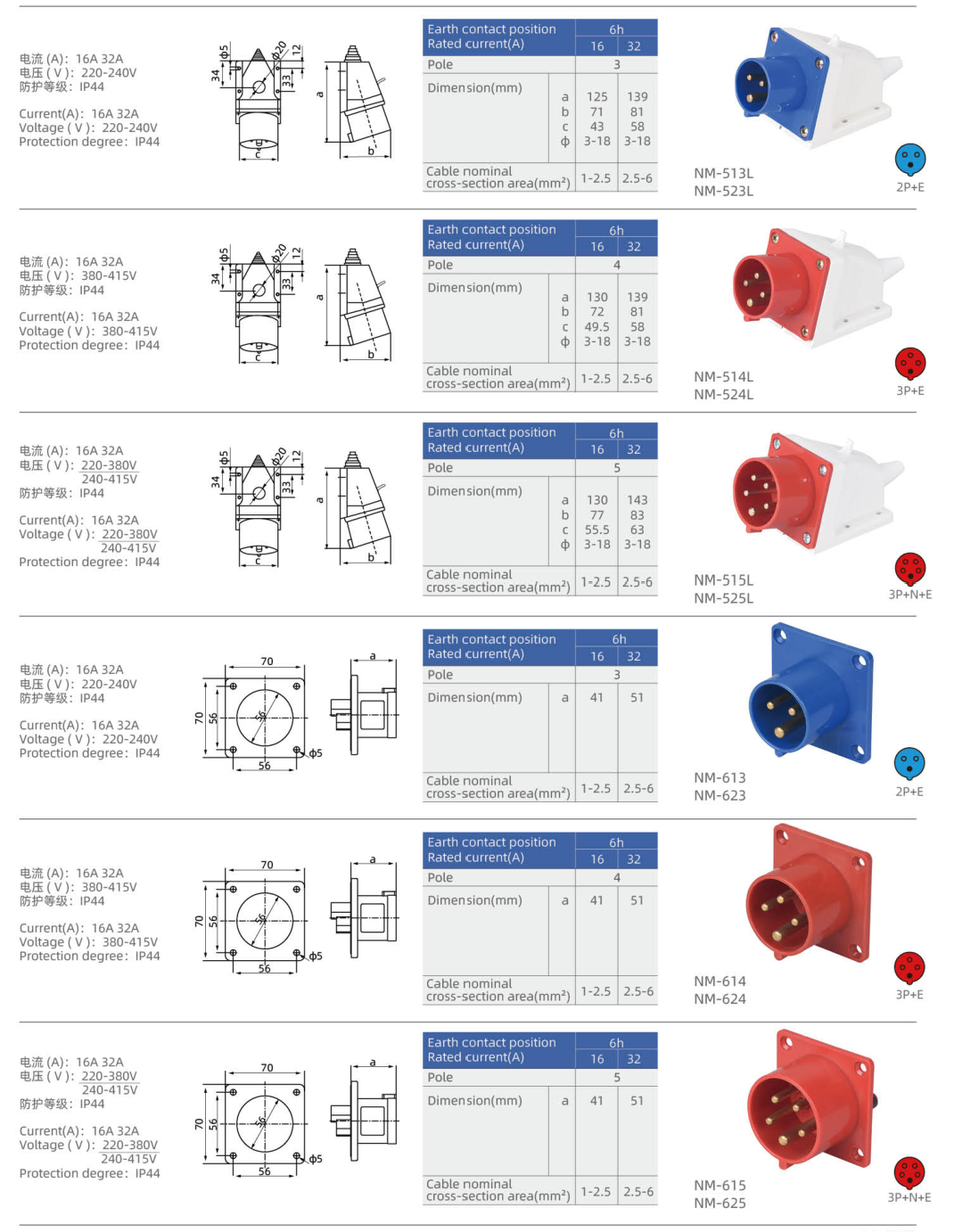
| NM-613 | Straight panel inlet | 16 | 2P+E | 220–240 V | 6h | Mavi | 1–2.5 |
| NM-623 | Straight panel inlet | 32 | 2P+E | 220–240 V | 6h | Mavi | 2.5–6 |
| NM-614 | Straight panel inlet | 16 | 3P+E | 380–415 V | 6h | Kırmızı | 1–2.5 |
| NM-624 | Straight panel inlet | 32 | 3P+E | 380–415 V | 6h | Kırmızı | 2.5–6 |
| NM-615 | Straight panel inlet | 16 | 3P+N+E | 220–380 V / 240–415 V | 6h | Kırmızı | 1–2.5 |
| NM-625 | Straight panel inlet | 32 | 3P+N+E | 220–380 V / 240–415 V | 6h | Kırmızı | 2.5–6 |
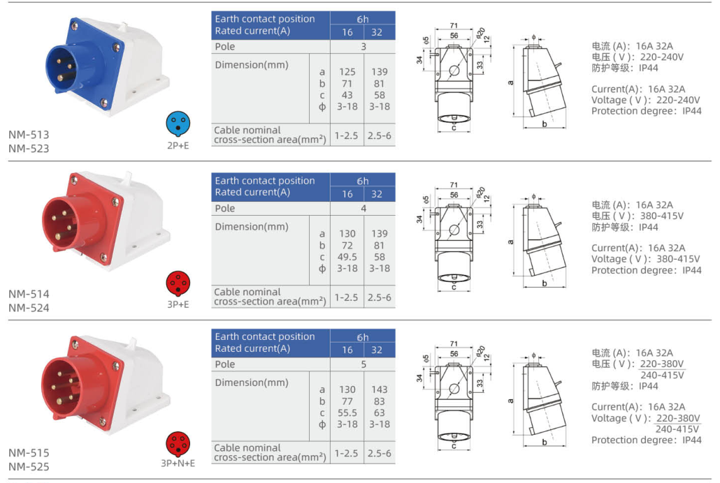
| NM-513 | Surface inlet with angled face | 16 | 2P+E | 220–240 V | 6h | Mavi | 1–2.5 |
| NM-523 | Surface inlet with angled face | 32 | 2P+E | 220–240 V | 6h | Mavi | 2.5–6 |
| NM-514 | Surface inlet with angled face | 16 | 3P+E | 380–415 V | 6h | Kırmızı | 1–2.5 |
| NM-524 | Surface inlet with angled face | 32 | 3P+E | 380–415 V | 6h | Kırmızı | 2.5–6 |
| NM-515 | Surface inlet with angled face | 16 | 3P+N+E | 220–380 V / 240–415 V | 6h | Kırmızı | 1–2.5 |
| NM-525 | Surface inlet with angled face | 32 | 3P+N+E | 220–380 V / 240–415 V | 6h | Kırmızı | 2.5–6 |
| NM-513L | Surface inlet with angled face — L housing | 16 | 2P+E | 220–240 V | 6h | Mavi | 1–2.5 |
| NM-523L | Surface inlet with angled face — L housing | 32 | 2P+E | 220–240 V | 6h | Mavi | 2.5–6 |
| NM-514L | Surface inlet with angled face — L housing | 16 | 3P+E | 380–415 V | 6h | Kırmızı | 1–2.5 |
| NM-524L | Surface inlet with angled face — L housing | 32 | 3P+E | 380–415 V | 6h | Kırmızı | 2.5–6 |
| NM-515L | Surface inlet with angled face — L housing | 16 | 3P+N+E | 220–380 V / 240–415 V | 6h | Kırmızı | 1–2.5 |
| NM-525L | Surface inlet with angled face — L housing | 32 | 3P+N+E | 220–380 V / 240–415 V | 6h | Kırmızı | 2.5–6 |
P denotes a phase contact, N neutral and E protective earth. A dash means that no voltage is assigned in this selection table.
Boyut
| Model | Lettered outline dimensions (mm) | Fixed mounting geometry |
|---|---|---|
| NM-613K | a=50, b=60 | Flange width × height (mm): 76 × 76; Fixing centres (mm): 60 × 60; Panel opening diameter (mm): 65; Fixing hole diameter (mm): 5 |
| NM-623K | a=59, b=60 | Flange width × height (mm): 76 × 76; Fixing centres (mm): 60 × 60; Panel opening diameter (mm): 65; Fixing hole diameter (mm): 5 |
| NM-614K | a=50, b=60 | Flange width × height (mm): 76 × 76; Fixing centres (mm): 60 × 60; Panel opening diameter (mm): 65; Fixing hole diameter (mm): 5 |
| NM-624K | a=59, b=60 | Flange width × height (mm): 76 × 76; Fixing centres (mm): 60 × 60; Panel opening diameter (mm): 65; Fixing hole diameter (mm): 5 |
| NM-615K | a=50, b=60 | Flange width × height (mm): 76 × 76; Fixing centres (mm): 60 × 60; Panel opening diameter (mm): 65; Fixing hole diameter (mm): 5 |
| NM-625K | a=59, b=60 | Flange width × height (mm): 76 × 76; Fixing centres (mm): 60 × 60; Panel opening diameter (mm): 65; Fixing hole diameter (mm): 5 |
| NM-613 | a=41 | Flange width × height (mm): 70 × 70; Fixing centres (mm): 56 × 56; Panel opening diameter (mm): 46; Fixing hole diameter (mm): 5 |
| NM-623 | a=51 | Flange width × height (mm): 70 × 70; Fixing centres (mm): 56 × 56; Panel opening diameter (mm): 46; Fixing hole diameter (mm): 5 |
| NM-614 | a=41 | Flange width × height (mm): 70 × 70; Fixing centres (mm): 56 × 56; Panel opening diameter (mm): 46; Fixing hole diameter (mm): 5 |
| NM-624 | a=51 | Flange width × height (mm): 70 × 70; Fixing centres (mm): 56 × 56; Panel opening diameter (mm): 46; Fixing hole diameter (mm): 5 |
| NM-615 | a=41 | Flange width × height (mm): 70 × 70; Fixing centres (mm): 56 × 56; Panel opening diameter (mm): 46; Fixing hole diameter (mm): 5 |
| NM-625 | a=51 | Flange width × height (mm): 70 × 70; Fixing centres (mm): 56 × 56; Panel opening diameter (mm): 46; Fixing hole diameter (mm): 5 |
| NM-513 | a=125, b=71, c=43, Φ=3–18 | — |
| NM-523 | a=139, b=81, c=58, Φ=3–18 | — |
| NM-514 | a=130, b=72, c=49.5, Φ=3–18 | — |
| NM-524 | a=139, b=81, c=58, Φ=3–18 | — |
| NM-515 | a=130, b=77, c=55.5, Φ=3–18 | — |
| NM-525 | a=143, b=83, c=63, Φ=3–18 | — |
| NM-513L | a=125, b=71, c=43, Φ=3–18 | — |
| NM-523L | a=139, b=81, c=58, Φ=3–18 | — |
| NM-514L | a=130, b=72, c=49.5, Φ=3–18 | — |
| NM-524L | a=139, b=81, c=58, Φ=3–18 | — |
| NM-515L | a=130, b=77, c=55.5, Φ=3–18 | — |
| NM-525L | a=143, b=83, c=63, Φ=3–18 | — |
Use the lettered dimensions with the matching inlet outline. Flange geometry and housing size differ between body versions; select the complete model code when checking installation space.
Bağlantı Seçimi
Match rated current, contact configuration, voltage and earth-contact position at both sides of the connection. Select panel or surface mounting before comparing the housing dimensions. The IP rating applies to the correctly assembled connection with its compatible mating interface; maintain the specified sealing and closure arrangement.
Sipariş Bilgileri
Send YOCL ELECTRIC the full model code, required quantity, supply voltage, contact configuration and installation arrangement. Include conductor cross-section and the mating cable connector when requesting a complete equipment power connection.