
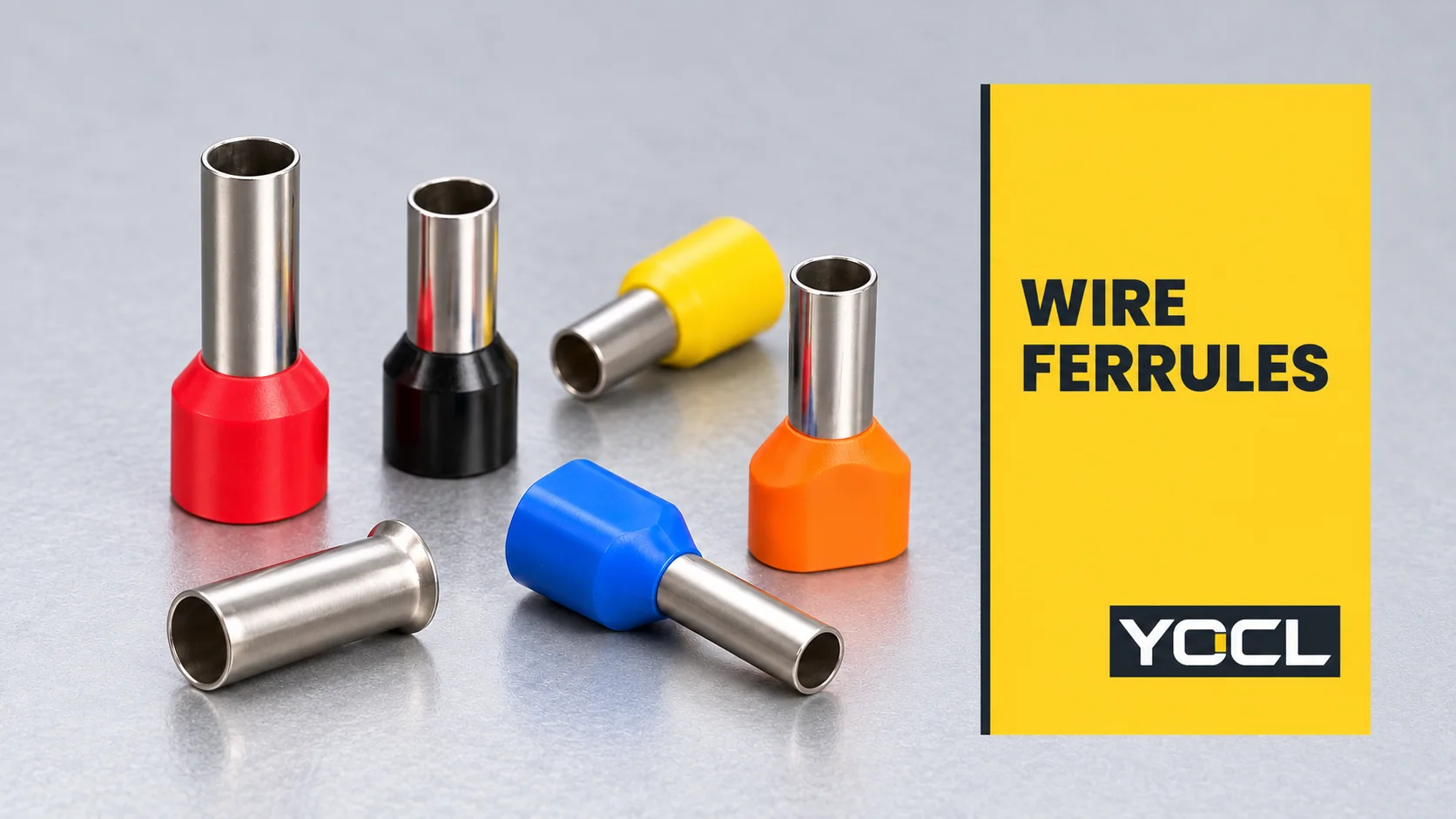
A wire ferrule is a tubular metal sleeve crimped around the stripped strands of a conductor to prepare its end for insertion into a compatible terminal. It gathers the strands into a contained end. The terminal still provides the clamping connection; the ferrule’s type, size and finished shape must suit that connection.
Also called a bootlace ferrule, wire-end sleeve or cord-end ferrule, this component is specified by more than collar colour. To understand a ferrule, separate its conductor capacity, sleeve geometry and permitted use in the receiving terminal.
What does a wire ferrule do?
The metal sleeve surrounds the exposed conductor strands. Crimping forms the sleeve around them so the prepared end can be handled and inserted as one contained bundle. In a collared version, the plastic entry surrounds the wire-entry end; the projecting metal portion enters the terminal’s contact area.
The public scope of UL 486F, Bare and Covered Ferrules describes ferrules as conductor-end preparation that facilitates stranded-wire connection and prevents strands turning back during insertion. It covers designs for one stranded copper conductor or two of the same size.
This function is different from a lug bolted onto a stud or a connector joining two cable ends. A ferrule prepares the end for another connection device. UL 486F also separates ferrules from pin adapters covered by other connector standards; a similar-looking metal end does not establish interchangeability.
DIN 46228-4:2020-03 identifies tubular end-sleeves with plastic sleeves. Its official introduction explains strand containment and easier terminal insertion. That supports the component’s purpose, without establishing that every terminal requires one.
The main wire ferrule types
The most useful first distinction is one conductor or two, followed by collared or uncollared construction. YOCL’s catalogue organizes these into E, EN and TE series:
| Construction | Visible arrangement | What needs separate checking |
|---|---|---|
| E insulated single-wire ferrule | One tubular sleeve with an insulating collar | Single-conductor size, sleeve length and collar clearance |
| EN uninsulated single-wire ferrule | Bare metal sleeve with a flared entry | Conductor size, tube dimensions and the equipment’s insulation arrangement |
| TE insulated twin-wire ferrule | A common sleeve and broader collar for two conductors | The size of each conductor and acceptance of the finished two-wire termination |
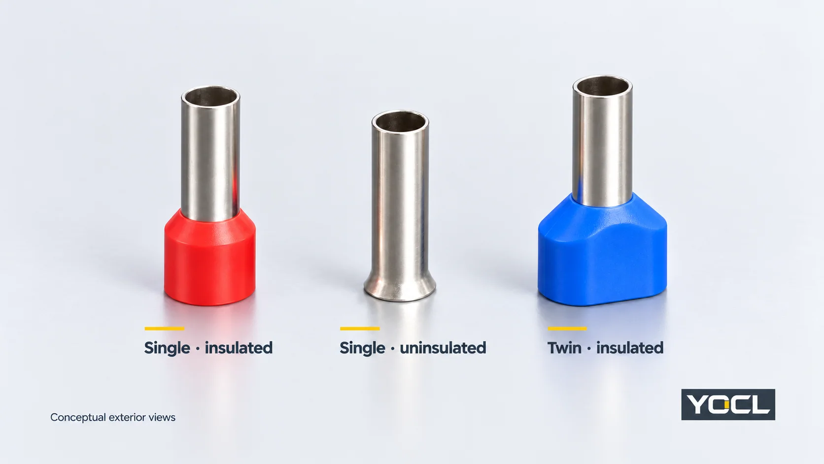
These are YOCL series names, rather than a universal naming system for every supplier. “Insulated” identifies the collar construction; it does not supply a voltage rating for the completed connection. Likewise, “twin” identifies the intended conductor arrangement, rather than permission to put two wires into any terminal.
How to read a wire ferrule size
Conductor area is different from diameter
A designation such as 1.5 mm² refers to conductor cross-sectional area. It is not the cable’s outside diameter, the ferrule’s bore diameter or the diameter of its plastic collar.
Read the ferrule’s declared conductor size alongside its drawing. The conductor determines the capacity needed inside the sleeve; the ferrule’s external dimensions affect the space needed at the terminal. Cable insulation and collar geometry add another fit question at the entry.
American Wire Gauge (AWG) is another conductor-size designation. Use the exact AWG or metric sizes declared for the chosen product and conductor. A catalogue pairing is not a reason to assume every nearby AWG/mm² size is an approved substitute.
Sleeve length is different from overall length
Ferrules of the same conductor capacity can have different sleeve lengths. On YOCL’s E-series drawing, F identifies the sleeve-length segment and L the overall length including the collar. These letter labels belong to that drawing; check the exact series before transferring their meanings.
The published E-series and TE-series tables provide a useful example:
| YOCL model | Declared conductor arrangement | F sleeve length | L overall length |
|---|---|---|---|
| E1508 | One × 1.5 mm² | 8.0 mm | 15.0 mm |
| E1512 | One × 1.5 mm² | 12.0 mm | 19.0 mm |
| TE 1508 | Two × 1.5 mm² | 8.0 mm | 15.5 mm |
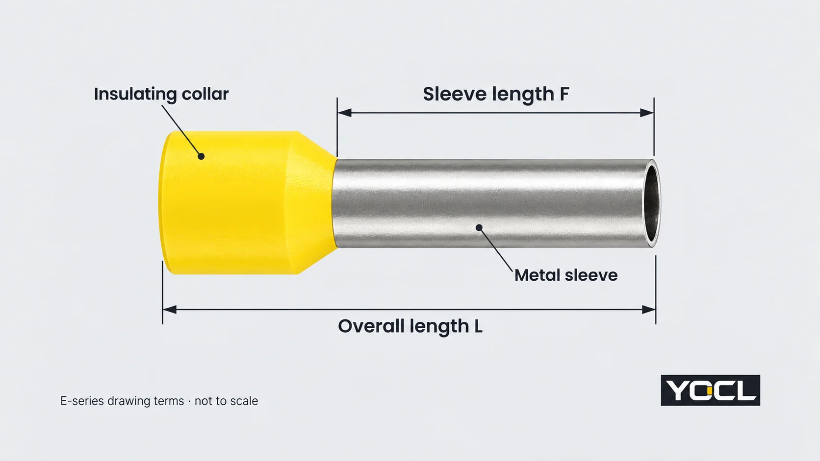
These are catalogue dimensions, not measurements of an installed connection. E1508 and E1512 accept the same declared conductor area but have different lengths. TE 1508 shares an 8 mm F dimension with E1508 while describing a different conductor arrangement. Neither area nor sleeve length alone determines terminal compatibility.
The receiving terminal’s insertion depth and preparation instructions determine which length is appropriate. Overall length cannot substitute for sleeve length when comparing the metal portion with the terminal’s contact space.
Twin notation and collar colour need their own reading
2 × 1.5 mm² means two conductors, each 1.5 mm². Their nominal areas add to 3 mm², but that arithmetic does not turn the twin ferrule into a single-wire 3 mm² model. Entry geometry, sleeve capacity, tooling and the permitted terminal arrangement remain separate requirements.
Colour is useful only within the specified catalogue coding. YOCL’s E-series lists colour options by size group. Its TE 7508 and TE 7510 models both declare 2 × 0.75 mm², yet list blue and grey collars respectively. Confirm the model and conductor designation rather than selecting a ferrule from colour alone.
What makes a ferrule compatible with a terminal?
Compatibility involves three interfaces:
- Conductor to ferrule: the conductor material, size and count must match the ferrule’s declared arrangement.
- Ferrule to crimping tool: the applicable tool and die must produce the required termination for that ferrule. Tool capacity alone does not establish the correct finished profile.
- Finished ferrule to terminal: the receiving device must permit the prepared conductor arrangement and accommodate its sleeve, crimp profile and collar.
“Screw terminal”, “spring terminal” and “push-in terminal” name connection mechanisms. They do not provide a universal answer to whether a ferrule is required, optional or unsuitable. Use the exact device’s instructions and any declared range for ferruled conductors. A ferrule that physically enters the opening has passed only a geometry check.
There is also an explicit scope boundary: UL 486F’s public scope excludes insulation-displacement connection (IDC) terminal blocks. Do not treat a prepared metal sleeve as a general replacement for the insulated wire that an IDC contact is designed to engage.
For a twin ferrule, verify acceptance of the two-conductor arrangement and its finished dimensions. A larger opening, a sufficient nominal area or a broad plastic collar cannot supply that authorization. Square and hexagonal crimp names also need to be checked against the actual ferrule, tooling and terminal documentation; neither is a universal compatibility rule.
What do standards and certification tell you?
Standard identity, product dimensions and connection approval answer different questions. DIN’s published title identifies a construction family; UL 486F’s public scope identifies its intended use and exclusions. A supplier’s reference to either standard is not, by itself, a model-specific certification record.
UL Solutions’ explanation of Component Recognition distinguishes a component’s assessment from certification of a complete end product. Recognized components have conditions of acceptability governing their use. Where certification is required, check the exact product record and applicable conditions alongside the receiving equipment’s documentation.
The YOCL dimensions above are first-party product declarations. They help interpret size fields; this article does not assert UL certification, a current rating or an approved terminal combination for those models.
Which document should you check next?
| Your question | The next document to use |
|---|---|
| Which construction describes the part I need? | The single, bare or twin product-family information |
| What conductor does this model accept? | Its declared conductor size, material and count |
| What do its length and diameter fields mean? | The exact model/series drawing and dimension table |
| Which tool produces the required crimp? | The applicable ferrule and tooling instructions |
| Is the prepared end permitted in my terminal? | The exact receiving device’s wiring instructions and connection data |
| What evidence covers the intended equipment or market? | Relevant model certification records, conditions and equipment requirements |
The YOCL wire-ferrule catalogue routes these construction and dimension questions to the E, EN and TE product information. When asking for a model review, include the conductor size and count, required sleeve length and receiving terminal reference so the enquiry describes the complete interface.
References
- UL Standards & Engagement — UL 486F: Bare and Covered Ferrules, Edition 3, 2024, revised August 2026. Official public scope, §§1.2, 1.6 and 1.8; function, conductor arrangement and exclusions.
- DIN Media — DIN 46228-4:2020-03: Tubular end-sleeves with plastic sleeve. Official publication identity and public introduction; the paid full standard was not consulted.
- YOCL product information — E Series Pre-Insulated Wire Ferrules. Construction, model dimensions, drawing and declared colour options.
- YOCL product information — EN Non-Insulated Cord End Ferrules. Bare flared-entry construction and dimension fields.
- YOCL product information — TE Twin Cord End Connectors. Two-conductor notation, model dimensions and model-specific collar colours.
- UL Solutions — The UL Component Recognition Classification. Component conditions of acceptability and the end-product certification boundary.