
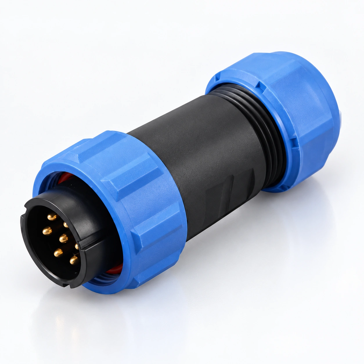
Threaded coupling
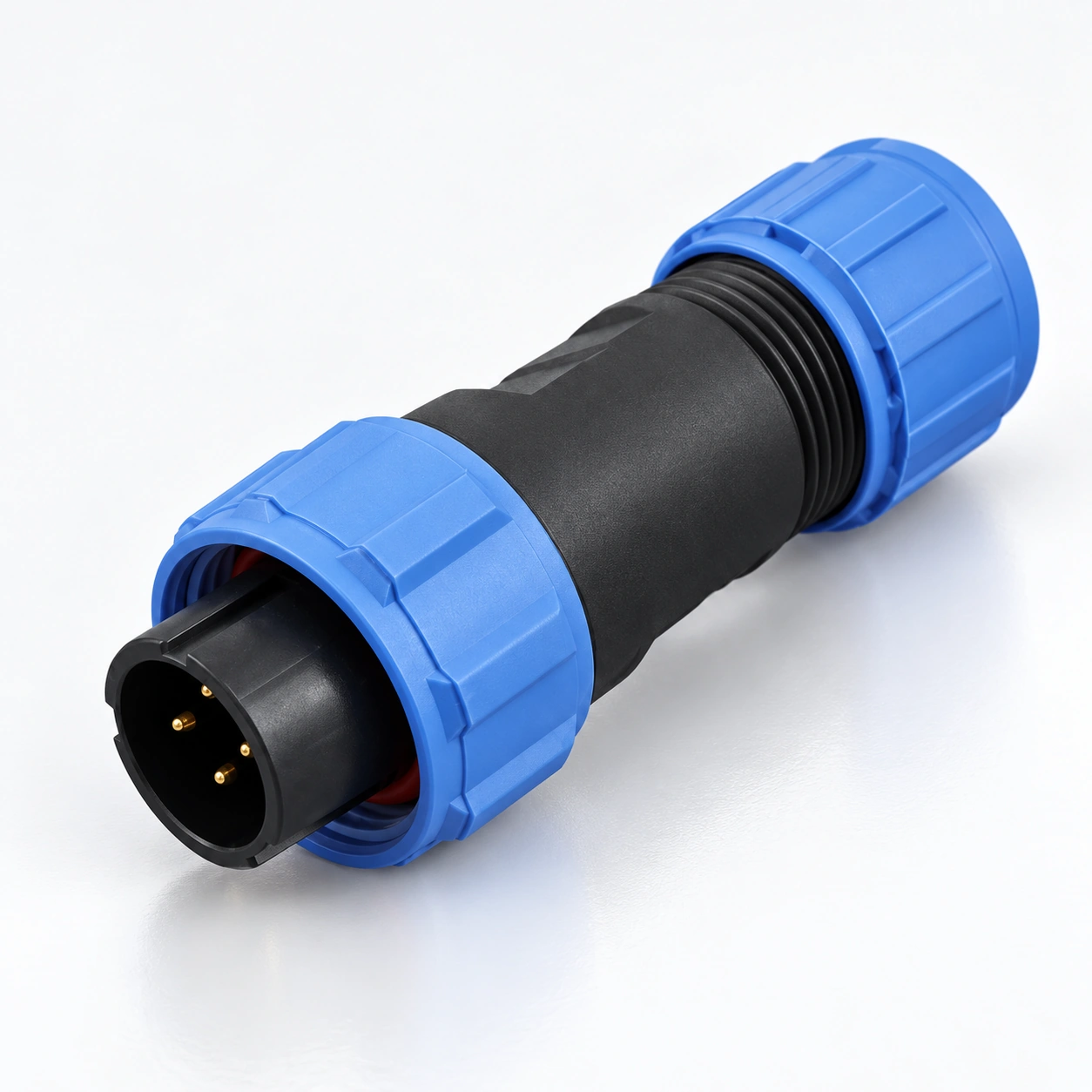
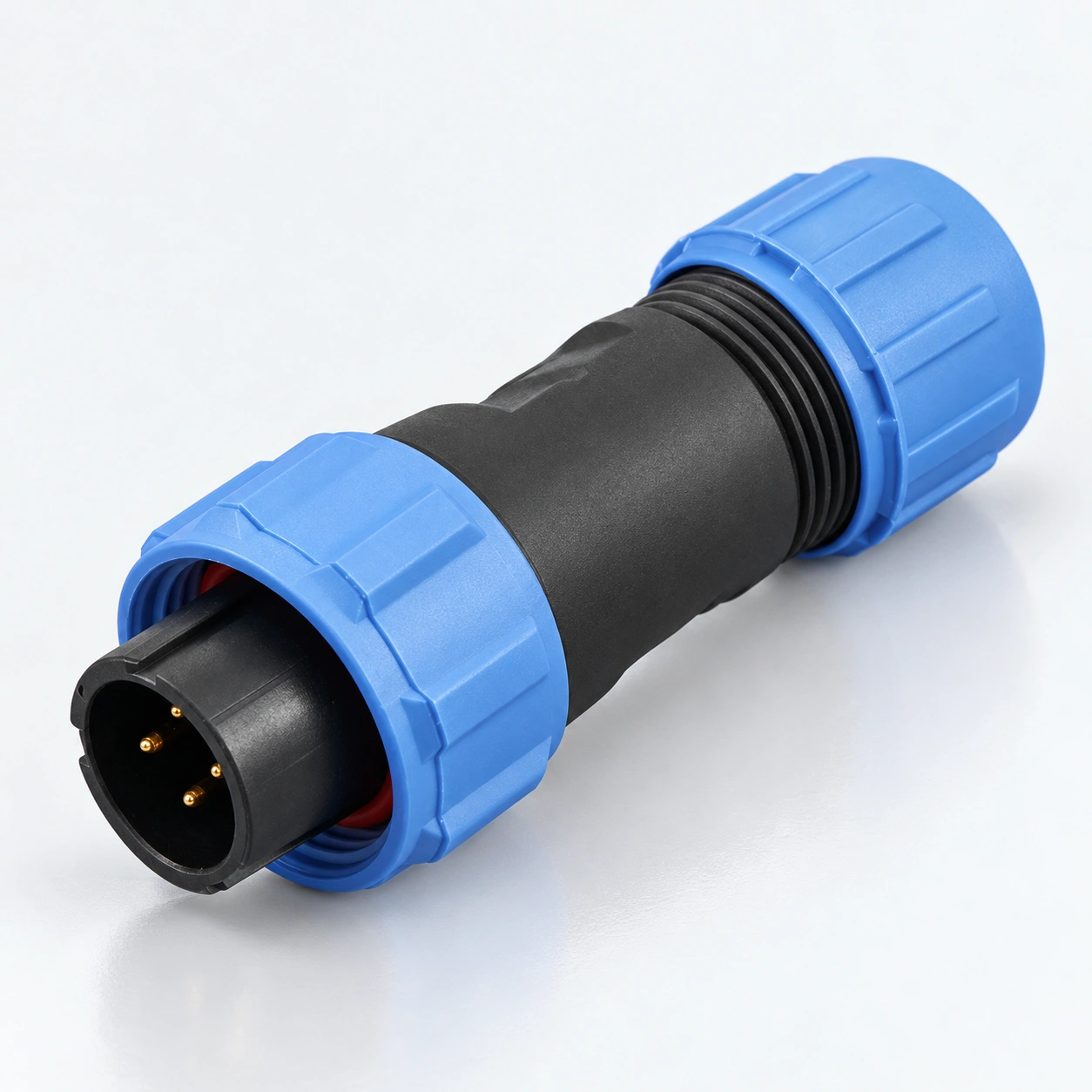
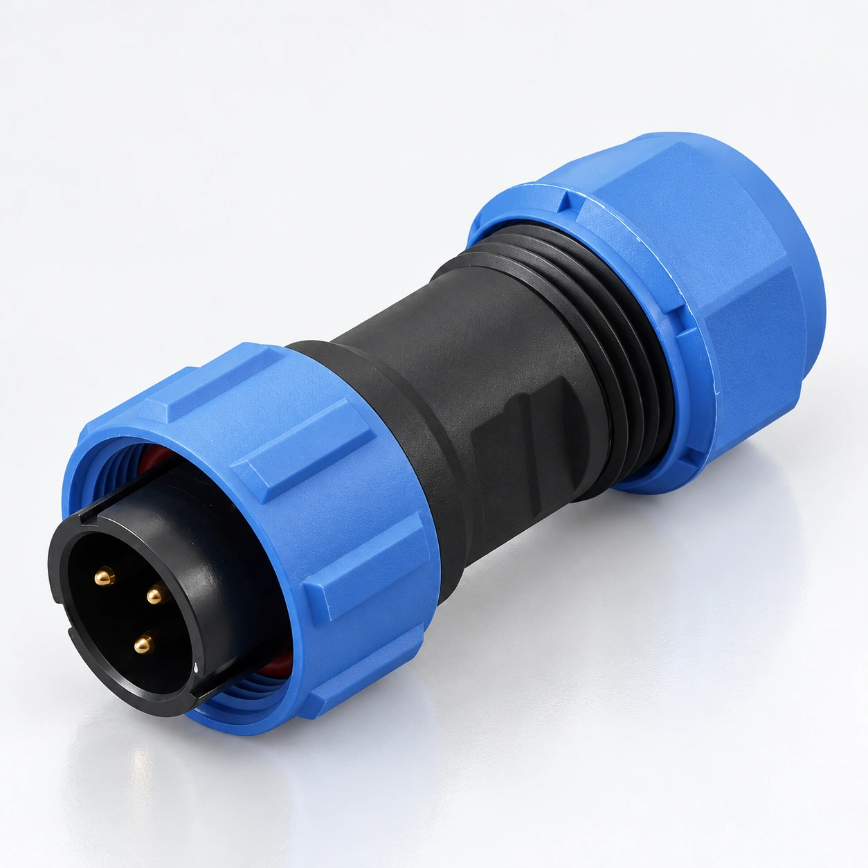
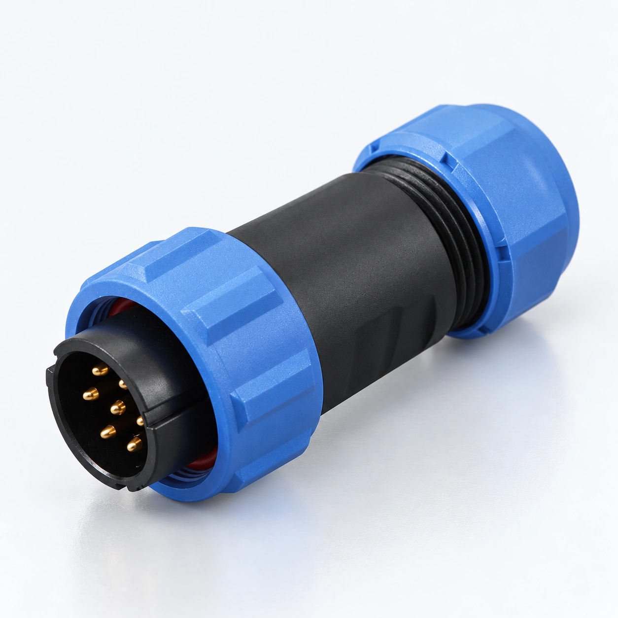
The coupling nut joins the matching connector bodies. Match the body family and contact arrangement before mating.
SP11, SP13, SP17, SP21 and SP29 circular connectors use threaded coupling for detachable cable and panel connections. Select the size, contact arrangement, cable seal and termination together. The catalogue lists IP68 protection; confirm the assembly and exposure conditions for your selected configuration.
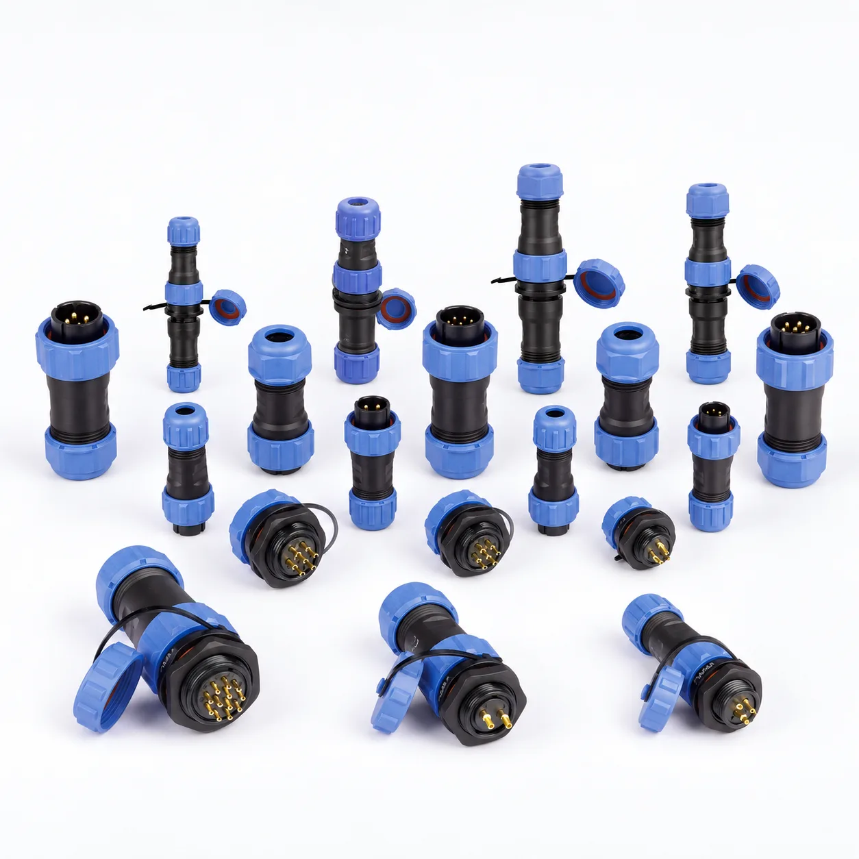
| Construction | Selection focus | Series reference |
|---|---|---|
| SP11 · Compact cable and panel | 2, 3, 4 or 5 contacts with solder termination. Cable seal range: 4–6.5 mm. Cable plug, inline socket, rear-nut panel socket and flange formats are listed. | SP1110 · SP1111 · SP1112 · SP1113 |
| SP13 · More contact arrangements | 2, 3, 4, 5, 6, 7 or 9 contacts. Type I cable seals cover 4–6.5 mm; Type II covers 5–8 mm. Select the current, working voltage and wire limit from the same contact row. | SP1310 · SP1311 · SP1312 · SP1313 |
| SP17 · Straight and angled formats | 2, 3, 4, 5, 7, 9 or 10 contacts. Straight plug and inline socket cable OD: 6–10 mm. Solder and crimp availability depends on the connector; solder ratings are not crimp ratings. | SP1710–SP1716 body families |
| SP21 · Cable and panel options | 2, 3, 4, 5, 7, 9 or 12 contacts. Cable seal options: 4.5–7 mm or 7–12 mm. Select the termination and conductor limit for the exact contact insert. | SP2110–SP2116 body families |
| SP29 · Larger cable entry | 2, 3, 4, 5, 7, 9 or 12 contacts. Straight plug and inline socket cable OD: 13–16 mm. Confirm the cable range for an angled version separately. | SP2910–SP2916 body families |
Understand the coupling, cable seal and panel fixing before selecting a configuration.
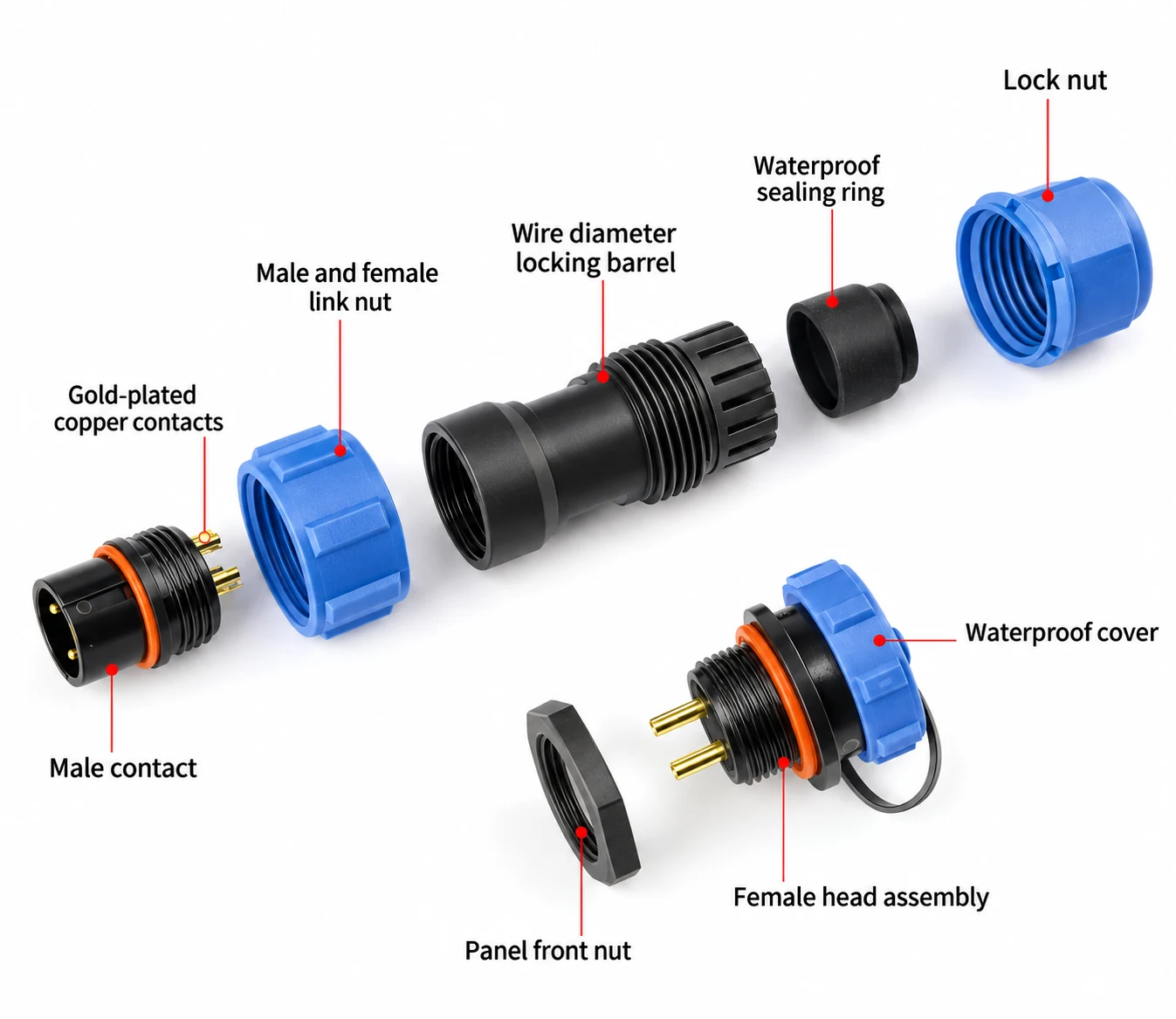
The coupling nut joins the matching connector bodies. Match the body family and contact arrangement before mating.
The rear clamping components and sealing ring must fit the actual cable jacket. Select the correct seal range and follow the model's assembly instructions.
The catalogue specifies gold-plated copper contacts. Solder, screw and crimp options depend on the series and insert; use configuration-specific wiring data.
Panel nuts, seals and protective caps depend on the body format. Confirm panel thickness, cutout and the specified protection condition rather than assuming a universal fit.
A series number or pin count alone does not define the complete connector specification.
Choose the required contact count, rated current and AC working voltage from the same configuration. One-minute dielectric withstand voltage is a test parameter, not the operating voltage.
SP11 and SP13 listings use solder termination. Larger families list configuration-dependent alternatives. Confirm solder, screw or crimp availability and conductor limits rather than transferring ratings between them.
Measure the complete cable jacket. Choose the specified seal option for the selected body; conductor cross-section is a different measurement.
Match the body family and complementary P/S contacts. Check panel thickness, cutout shape and mounting holes using the exact socket drawing.
Send the SP series, body designation, contact count, P/S contact type, termination, wire size, cable diameter and quantities for both mating sides.
Prepare an enquiryAgree the specification and required evidence before placing your order.
Explore manufacturingList both mating body references, contact count and pin/socket designation. Base codes do not include every ordering choice.
Include jacket diameter, conductor size, wire preparation and required termination method.
Provide the panel drawing, thickness, available mating space and required environmental test conditions.
Confirm sample fit, applicable ratings and documents, accessories, packing quantities and destination.
OEM & PACKING
Build your sp waterproof circular connectors order around the selected models, identification and supply requirements.
List both mating body references, contact count and pin/socket designation. Base codes do not include every ordering choice.
Provide part numbers, label artwork and any batch or traceability information required for the order.
Specify quantities per model, individual packs, outer cartons and delivery destination.
SP uses threaded coupling. LP uses a pushbutton snap-lock mechanism. Do not assume the series can mate with one another or share electrical ratings.
P identifies pin contacts and S identifies socket contacts. These are electrical contact types, separate from whether the body is a cable plug, inline socket or panel socket. Specify both body style and contact type.
No cross-size compatibility is claimed. Match the series, listed mating body family, contact count and complementary contacts.
No immersion depth or duration is established by the IP68 label alone. Confirm the selected assembly, cable seals, mating or cap condition and applicable test conditions before specifying the installation.
No. Current and working voltage vary with contact arrangement and termination. In particular, confirm the termination-specific current for SP21 and SP29 two- to five-contact configurations before ordering.
Not automatically. A termination legend indicates possible options, not identical ratings or availability for every insert. Request the exact configuration's conductor and electrical data.
Each linked SP product page contains its body and panel-opening information. Use the selected socket's panel drawing, not the external connector diameter or mounting thread alone.
No. Housing material flammability and complete-product certification are different matters. Request applicable model-specific evidence when the project requires it.
Send the SP series, body designation, contact count, P/S contact type, termination, wire size, cable diameter and quantities for both mating sides. Include the exact model quantities, delivery destination and required documentation.
Send your part numbers, label artwork, pack quantities and shipment requirements. Feasibility, sample requirements, minimum quantities and lead time are confirmed for the requested models.