
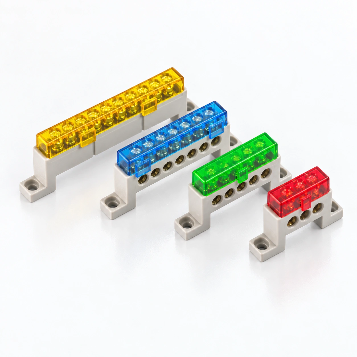
YCA10 Covered Brass Terminal Bars
YOCL ELECTRIC YCA10 covered brass terminal bars offer 18 paired configurations with 3–15 ways and 7×11 mm or 9×15 mm physical bar sections. PC and ABS plastic settings have separate temperature specifications. Select the complete arrangement by way count, bar section, screw size and mounting dimensions.
Overview
YOCL ELECTRIC YCA10 terminal bars provide a common brass conductor with plastic supports and a cover. Eighteen configurations combine 3 to 15 connection ways with either a 7×11 mm or 9×15 mm brass section. PC and ABS are the specified plastic materials, while bar size, screw size and body dimensions are paired for each configuration.
Features
- Two physical brass sections: 7×11 mm and 9×15 mm.
- 3, 4, 5, 6, 7, 8, 10, 12 or 15 ways in each section group.
- PC and ABS plastic materials with separate temperature specifications.
- Zinc-plated iron screws in M5×9 or M5×12 sizes, paired with bar section.
- Covered common-bar structure with supports for panel positioning.
Technical Specifications
| Parameter | Specification |
|---|---|
| Brand | YOCL ELECTRIC |
| Series | YCA10 |
| Conductor | Brass |
| Screws | Zinc-plated iron |
| Plastic setting | PC; ABS |
| PC material temperature | -40°C to +85°C |
| ABS material temperature | -20°C to +70°C |
| Operating voltage range | 250–450 V |
| Connection function | Common-potential bar |
| Bar sections | 7×11 mm; 9×15 mm |
Model options
| Model | Ways | Bar w×h (mm) | L (mm) | L1 (mm) | L2 (mm) | H (mm) | W (mm) | Φ (mm) | Screw size | Plastic setting |
|---|---|---|---|---|---|---|---|---|---|---|
| YCA10 | 3 | 7×11 | 26.5 | 56 | 46 | 36 | 15 | 6.5 | M5×9 | PC, ABS |
| YCA10 | 4 | 7×11 | 34.5 | 64 | 54 | 36 | 15 | 6.5 | M5×9 | PC, ABS |
| YCA10 | 5 | 7×11 | 42.5 | 72 | 62 | 36 | 15 | 6.5 | M5×9 | PC, ABS |
| YCA10 | 6 | 7×11 | 50.5 | 80 | 70 | 36 | 15 | 6.5 | M5×9 | PC, ABS |
| YCA10 | 7 | 7×11 | 58.5 | 88 | 78 | 36 | 15 | 6.5 | M5×9 | PC, ABS |
| YCA10 | 8 | 7×11 | 65.5 | 96 | 86 | 36 | 15 | 6.5 | M5×9 | PC, ABS |
| YCA10 | 10 | 7×11 | — | 112 | 102 | 36 | 15 | 6.5 | M5×9 | PC, ABS |
| YCA10 | 12 | 7×11 | 98.5 | 128 | 118 | 36 | 15 | 6.5 | M5×9 | PC, ABS |
| YCA10 | 15 | 7×11 | 102.5 | 152 | 142 | 36 | 15 | 6.5 | M5×9 | PC, ABS |
| YCA10 | 3 | 9×15 | 36.5 | 69.5 | 60 | 43 | 18 | 9(2×10) | M5×12 | PC, ABS |
| YCA10 | 4 | 9×15 | 47 | 80 | 70.5 | 43 | 18 | 9(2×10) | M5×12 | PC, ABS |
| YCA10 | 5 | 9×15 | 58 | 91 | 81.5 | 43 | 18 | 9(2×10) | M5×12 | PC, ABS |
| YCA10 | 6 | 9×15 | 68.5 | 102 | 92.5 | 43 | 18 | 9(2×10) | M5×12 | PC, ABS |
| YCA10 | 7 | 9×15 | 79.5 | 113 | 103 | 43 | 18 | 9(2×10) | M5×12 | PC, ABS |
| YCA10 | 8 | 9×15 | 90.5 | 124 | 114 | 43 | 18 | 9(2×10) | M5×12 | PC, ABS |
| YCA10 | 10 | 9×15 | 112 | 145.5 | 135 | 43 | 18 | 9(2×10) | M5×12 | PC, ABS |
| YCA10 | 12 | 9×15 | 133.5 | 167 | 157 | 43 | 18 | 9(2×10) | M5×12 | PC, ABS |
| YCA10 | 15 | 9×15 | 166 | 188.5 | 178.5 | 43 | 18 | 9(2×10) | M5×12 | PC, ABS |
Dimension
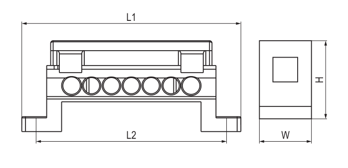
Use the configuration row for L, L1, L2, H, W and Φ in millimetres. The 7×11 mm group has H 36 mm and W 15 mm; the 9×15 mm group has H 43 mm and W 18 mm. Physical bar dimensions are separate from the conductor size required by the wiring design.
Selection
Choose the brass section and number of ways as one configuration, then compare its footprint and screw size. The PC and ABS temperature figures refer to those materials separately. Include any material-specific requirements with the configuration enquiry.
Ordering
Specify YCA10, the required number of ways, 7×11 mm or 9×15 mm bar section and quantity. Use the way count and bar section together to identify the required configuration.