
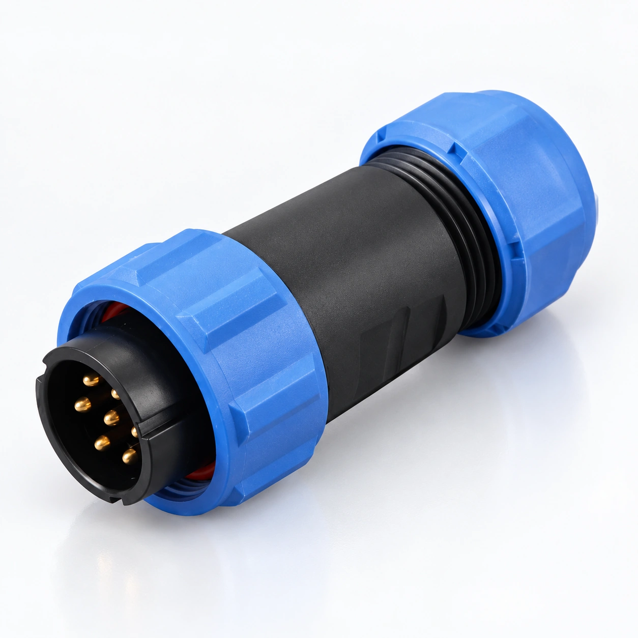
SP29 Waterproof Circular Connectors
YOCL ELECTRIC SP29 Waterproof Circular Connectors provide cable and equipment interfaces with threaded locking and selectable contact configurations.
- 2 / 3 / 4 / 5 / 7 / 9 / 12 contacts; pin and socket options.
- IP68 catalogue rating and −40 °C to +85 °C temperature range.
- Gold-plated copper contacts with PC / PA66 housings and PPS insulators.
- Straight and angled cable plugs, inline sockets and panel socket formats.
- Straight cable plug and inline cable socket: 13–16 mm cable outer diameter.
- Solder, screw-terminal and crimp options are configuration-dependent.
Overview
YOCL ELECTRIC SP29 Waterproof Circular Connectors provide detachable cable-to-cable and cable-to-panel electrical connections with 2, 3, 4, 5, 7, 9 or 12 contacts. A threaded coupling secures the mating bodies, while pin and socket contact options allow the required electrical arrangement to be selected.
The range includes straight and angled cable plugs, inline cable sockets, rear-nut panel sockets and flange-mounted sockets. The straight cable plug and inline cable socket are listed for 13–16 mm cable outer diameters. The catalogue lists IP68 protection, with electrical and wire-termination specifications selected by contact configuration.
Features
- Thread locking: A screw coupling joins the mating connector bodies.
- Seven contact-count options: Select 2, 3, 4, 5, 7, 9 or 12 contacts.
- Cable and panel body styles: Straight plugs, inline connections, angled plugs and equipment sockets are listed.
- Pin and socket contacts: P and S designations refer to electrical contact type.
- Gold-plated copper contacts: The catalogue specifies copper contacts with gold plating.
- Selectable termination: Solder, screw-terminal and crimp versions are listed, with configuration-specific limits.
Technical Specifications
| Parameter | Specification |
|---|---|
| Brand | YOCL ELECTRIC |
| Series | SP29 |
| Connector type | Waterproof circular connector |
| Contact counts | 2 / 3 / 4 / 5 / 7 / 9 / 12 |
| Coupling | Thread locking |
| Contact types | P: pin; S: socket |
| Housing materials | Thermoplastic PC / PA66 |
| Housing material fire rating | V-0 |
| Insulator | Thermoplastic PPS |
| Contacts | Gold-plated copper |
| Protection grade | IP68, catalogue rating |
| Catalogue mating-cycle figure | 500 |
| Temperature range | −40 °C to +85 °C |
| Insulation resistance | 2000 MΩ |
Electrical Contact Data
The following values come from the catalogue’s solder-contact parameter table. They are not a separate specification for crimp contacts.
| Contacts | Rated current | Contact diameter × count | Working voltage, AC | Withstand voltage, AC, 1 minute | Contact resistance |
|---|---|---|---|---|---|
| 2 | — | Ø3 mm × 2 | 500 V | 1500 V | 1 mΩ |
| 3 | — | Ø3 mm × 3 | 500 V | 1500 V | 1 mΩ |
| 4 | — | Ø3 mm × 4 | 500 V | 1500 V | 1 mΩ |
| 5 | — | Ø3 mm × 5 | 500 V | 1500 V | 1 mΩ |
| 7 | 15 A | Ø2 mm × 7 | 500 V | 1500 V | 2.5 mΩ |
| 9 | 5 A | Ø1 mm × 9 | 400 V | 1500 V | 5 mΩ |
| 12 | 5 A | Ø1 mm × 12 | 400 V | 1200 V | 5 mΩ |
For two- to five-contact configurations, obtain the current rating for the selected termination and part number when ordering. Working voltage and the one-minute withstand figure describe different parameters.
Conductor Limits by Termination
| Contacts | Solder conductor limit | Catalogue AWG entry | Screw-terminal conductor limit | Catalogue AWG entry |
|---|---|---|---|---|
| 2 / 3 / 4 / 5 | ≤4 mm² | 12 AWG | ≤1.5 mm² | 15 AWG |
| 7 | ≤2 mm² | 14 AWG | — | — |
| 9 / 12 | ≤0.75 mm² | 18 AWG | — | — |
The metric limits and AWG entries are reproduced as catalogue pairs. An em dash means no conductor limit is provided for that termination in this table. Select the wire size together with the contact insert and termination. Crimp-specific conductor limits are not specified here.
Cable Jacket Selection
| Applicable body styles | Listed cable outer diameter |
|---|---|
| SP2910 straight cable plugs and SP2911 inline cable sockets | 13–16 mm |
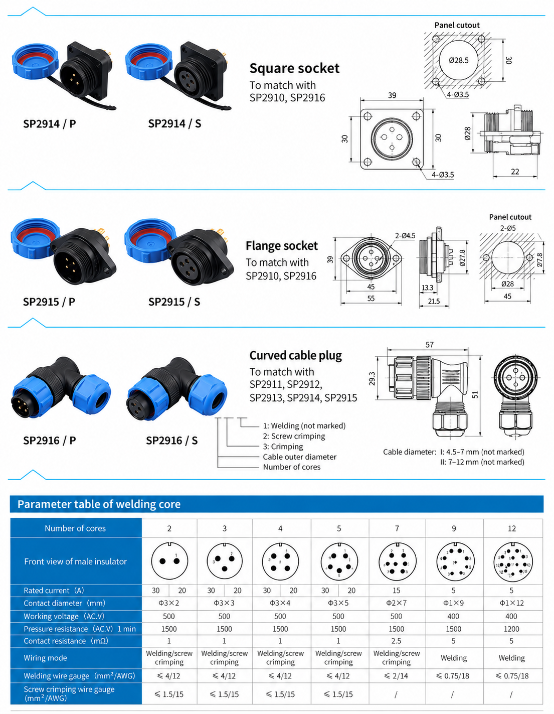
The angled SP2916 cable diameter is not specified here. Include the actual cable diameter when requesting that body style.
Dimension
Connector Body Dimensions
| Base model | Listed body dimensions |
|---|---|
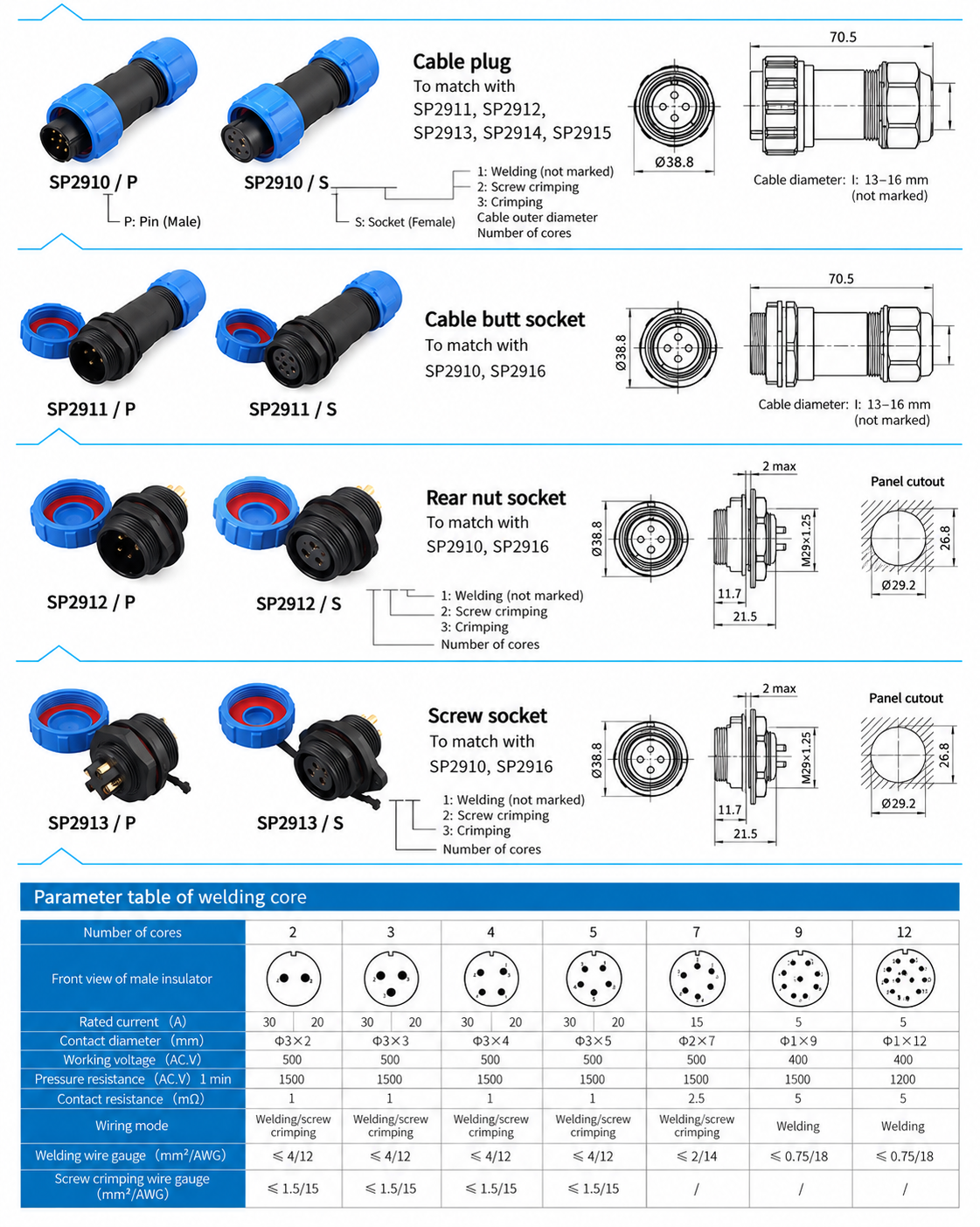
| SP2910 straight cable plug | 70.5 mm overall length; 38.8 mm front width |
| SP2911 inline cable socket | 70.5 mm overall length; Ø38.8 mm front diameter |
| SP2912 / SP2913 panel sockets | 21.5 mm overall length; M29 × 1.25 mounting thread; panel thickness 2 mm max. |
| SP2914 square-flange socket | 39 × 39 mm flange; 22 mm overall axial length; 30 mm mounting-hole pitch; Ø3.5 mm body mounting holes |
| SP2915 two-hole flange socket | 55 mm body width × 39 mm height; 45 mm hole pitch; two Ø4.5 mm body mounting holes; 21.5 mm overall length |
Panel Opening Dimensions
| Panel socket | Listed panel opening |
|---|---|
| SP2912 / SP2913 | Ø29.2 mm opening with 26.8 mm flat-to-flat height |
| SP2914 | 28.5 mm central opening; Ø3.5 mm mounting holes on the shown 30 mm pitch |
| SP2915 | Ø28 mm central opening; two Ø5 mm mounting holes on 45 mm centres |
Connector-body holes and panel mounting holes have separate dimensions. Use the selected socket’s complete installation drawing to check the opening shape and hole positions.
Connector Formats and Mating Families
| Base body model | Format | Listed mating family |
|---|---|---|
| SP2910 | Straight cable plug | SP2911 / SP2912 / SP2913 / SP2914 / SP2915 |
| SP2911 | Inline cable socket | SP2910 / SP2916 |
| SP2912 | Rear-nut panel socket | SP2910 / SP2916 |
| SP2913 | Panel socket, style 13 | SP2910 / SP2916 |
| SP2914 | Square-flange panel socket | SP2910 / SP2916 |
| SP2915 | Two-hole flange panel socket | SP2910 / SP2916 |
| SP2916 | Angled cable plug | SP2911 / SP2912 / SP2913 / SP2914 / SP2915 |
Each body family is shown with /P pin and /S socket contact options. Match the contact count and opposite electrical contact types as well as the body families when specifying a mating pair.
Ordering Information
Use the base body model and contact designation, such as SP2910/P for a straight cable plug with pin contacts or SP2914/S for a square-flange body with socket contacts. These are catalogue base designations; contact count, cable seal range and termination must also be specified.
The catalogue’s termination legend uses 1 for soldering (unmarked), 2 for screw termination and 3 for crimping. The presence of a termination in the legend does not establish that every body and contact-count combination is available in that form. Obtain the complete part number for the requested configuration.
Selection Guide
- Select the body style and mating body family.
- Specify pin or socket contacts and the required contact count on both sides.
- Select the termination and conductor size using the applicable limits.
- Match the cable seal to the cable jacket diameter; for panel versions, use the format-specific opening dimensions.
- Specify the required current, AC working voltage, quantity and mating-part requirements. Obtain model-specific data for a crimp version or a two- to five-contact current rating.
Applications
- Detachable equipment wiring.
- Inline cable connections.
- Panel-mounted electrical interfaces.
- Multi-contact power and signal connections.