
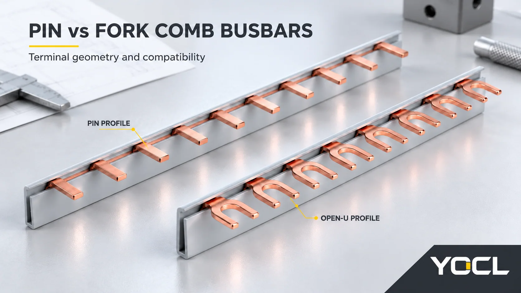
Choose a pin or fork comb busbar by the interface permitted for the exact receiving terminal and connection position. A pin needs the designated entry and capture geometry; an open fork needs a clamp intended to engage its arms. Both must match the contact dimensions, row spacing and circuit layout. Neither shape provides universal compatibility or a universal performance advantage.
The useful comparison holds the device model, terminal position, row and electrical duty constant, then changes the proposed comb. It answers two separate questions: does this contact match the interface, and is this complete combination documented for use?
Pin and Fork Geometry: What the Terminal Must Capture
“Pin” does not necessarily mean a round rod. The published exterior of the YOCL BS101 pin series shows narrow, flat projecting contacts. An open fork has two arms separated by a slot; the BS301 U-type series illustrates that open profile.
Catalogue names need care. YOCL separately names BS201 as C45 fork, although its gallery shows wider closed tabs. Preserve the series name and compare its drawing; the word “fork” alone does not prove an open U-shaped contact.
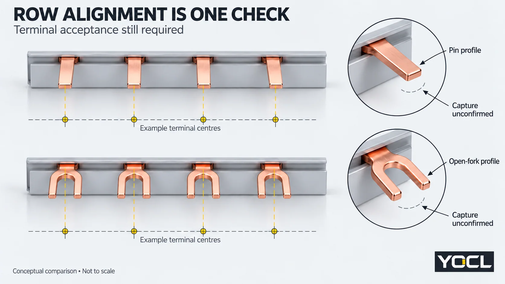
For either profile, entering the terminal mouth is only an entry check. The intended conductive surfaces must reach the specified clamping area at the required engagement depth. A visible screw cannot reveal every feature of the terminal behind it. Do not assume that a fork belongs around any screw, or that a wire opening accepts a flat pin.
The comb busbar overview explains the separate roles of contacts, poles and modules. Here, the decision is which contact can mate with the same receiving-device interface.
Compare Both Candidates Against One Terminal Record
Use the exact device instructions and terminal drawing, including the proposed connection side. “Candidate” below means the interface checks support further evaluation; it is not assembly approval.
| Evidence at the same terminal position | Pin candidate | Open-fork candidate | Decision boundary |
|---|---|---|---|
| Only the proposed pin interface is permitted; its dimensions and engagement agree | Retain | Exclude at this position | Complete the remaining combination checks |
| Only the proposed open-fork interface is permitted; its dimensions and engagement agree | Exclude at this position | Retain | Complete the remaining combination checks |
| Both interfaces are explicitly permitted, and each proposed contact matches | Retain | Retain | Compare both complete documented combinations |
| A required dimension, engagement or row position conflicts | Reject if affected | Reject if affected | If both conflict, neither is a match |
| Permitted interface, position or a critical dimension is unknown | Hold if unresolved | Hold if unresolved | Obtain the missing evidence before deciding |
A known conflict and missing information produce different outcomes. A wrong contact pitch rejects that candidate. An unspecified pitch leaves it on hold. Neither uncertainty nor a successful sample insertion establishes approval.
Compare Contact Dimensions and the Whole Row
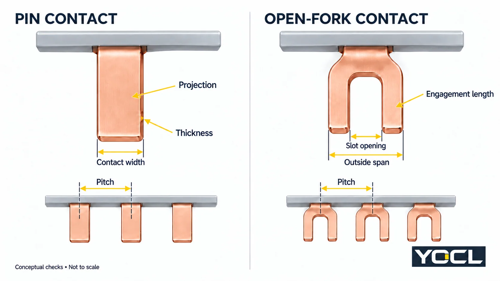
For a pin, compare the actual contact width, thickness and projection with the permitted entry, capture depth and position of the insulation shoulder.
For an open fork, compare the outside span, slot opening, arm dimensions, thickness and engagement length with the intended clamp. A slot that clears a feature can still leave the arms outside the specified contact area.
Record the drawing dimensions and their reference points rather than comparing two unlabelled “width” values. An overall conductor width, tooth width and fork-slot width describe different features. If the dimension mapping is unclear, request a clarified drawing.
Then compare the contact centres across the whole intended row. Check terminal height, device order and any gaps introduced by auxiliary equipment. Nominal module width, overall comb length or a shared DIN rail does not complete that comparison. Contact alignment must also follow the intended circuit sequence.
Identify whether the device permits the comb at the proposed top, bottom or dedicated connection position; do not assume those positions are interchangeable. Where a wire and busbar would share a terminal, obtain explicit permission for that conductor combination and arrangement.
Equal Catalogue Values Can Hide an Unresolved Interface
Consider these exact entries from YOCL’s BS101 and BS301 product tables:
| Published field | BS101-2 | BS301-2 |
|---|---|---|
| Catalogue designation | 1P pin | 1P U-type |
| Copper cross-section | 10 mm² | 10 mm² |
| Catalogue current capacity | 63 A | 63 A |
| Thickness, as labelled | 1.5 mm | 1.5 mm |
| Width, as labelled | 7 mm | 7 mm |
These are manufacturer declarations for those model rows. The shared fields do not identify an interchangeable contact. In particular, listed Width is not automatically tooth width, fork outside span or slot opening. The table alone does not establish pitch, capture depth or an approved receiving-device model.
For this comparison, a useful record is:
- Known: the declared model fields above.
- Awaiting evidence: exact terminal acceptance and position, mapped contact dimensions and engagement, complete row alignment, required insulation/accessories and documented combination.
- Present decision: two catalogue entries to evaluate; no approved replacement established.
If the actual device record permits only pin at that position and the BS101-2 geometry agrees, the pin remains a candidate and the open-fork alternative is excluded there. A fork-only record reverses that result. Without the device record, selecting between them from the shared 63 A entry leaves the interface question unanswered.
Confirm the Complete Device-and-Busbar Combination
In its September 2021 UK distribution-board explanation, the Institution of Engineering and Technology explains that individual product markings and conformity do not establish compatibility within an assembly. Different ranges from the same manufacturer can also require verification. Its stated routes include assurance from the original assembly manufacturer or an appropriate study of the proposed combination. This is scoped UK assembly guidance, not certification of a YOCL comb.
Keep electrical suitability separate from the geometric screen: confirm the selected combination’s current, voltage, feed arrangement, operating conditions and fault-duty evidence. Also resolve end caps, unused-contact protection and any permitted length treatment from the applicable product instructions. Do not infer cutting permission from the contact type.
For a review using the YOCL comb-busbar range, send the exact device code, terminal drawing, proposed comb drawing and device-row schedule together. That lets the review settle a pin, open-fork, both, neither or hold outcome against a defined interface.
References
- YOCL ELECTRIC — BS101 Series 1P Pin MCB Busbars: exterior profile and BS101-2 declared fields.
- YOCL ELECTRIC — BS301 Series 1P U-Type MCB Busbars: open-U exterior and BS301-2 declared fields.
- YOCL ELECTRIC — BS201 Series 1P C45 Fork MCB Busbars: separate catalogue designation and exterior reference.
- IET — Myth Busters #7, Wiring Matters, September 2021: UK assembly compatibility explanation.
- YOCL ELECTRIC — Comb Busbar Manufacturer: range and model-specific accessory/ordering boundaries.