
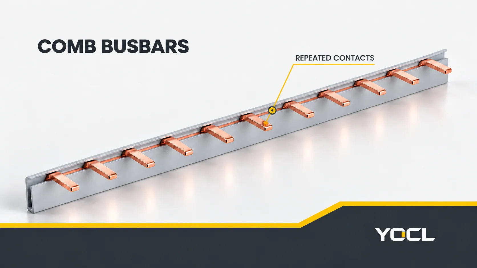
A comb busbar is a conductive distribution accessory with repeated projecting contacts, or “teeth,” that connect a supply path to a row of compatible modular devices. Insulated versions surround the longitudinal conductor while leaving the intended contact areas accessible. The comb makes electrical connections; the connected protective devices perform the switching or protection functions.
Pin and fork describe the contact interface. A designation such as 1P or 3P describes the electrical pole arrangement. Neither tells you, on its own, how many teeth are present or whether the comb fits a particular miniature circuit breaker (MCB). Read the accessory through three separate questions: contact shape, contact spacing and circuit sequence.
Pin and Fork Describe the Terminal Interface
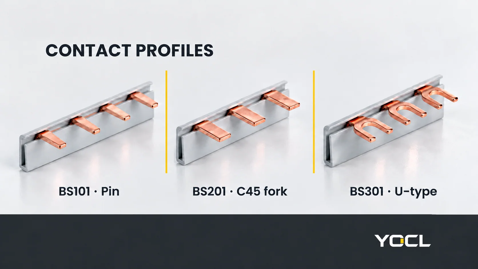
A pin-type comb has projecting contacts that enter the receiving terminal’s designated opening. “Pin” does not necessarily mean a round rod: the YOCL BS101 pin series uses narrow, flat projecting contacts in its published exterior image.
An open fork contact has two arms around an open slot. The receiving terminal must provide the intended clamping interface for that shape. A fork cannot be treated as a pin simply because both reach the same device row; the contact width, thickness, opening and engagement geometry differ.
Catalogue terminology deserves a closer look here. YOCL lists the BS201 C45 fork series separately from the BS301 U-type series. The BS201 gallery shows wider closed projecting tabs; the BS301 gallery shows open U-shaped contacts. The family name alone therefore cannot establish the exact slot or clamping geometry.
Use the model drawing and receiving-device instructions to resolve the interface. Keep the catalogue designation in an enquiry, alongside a clear contact-end view; do not replace it with an assumed equivalent name.
This also explains why “Which is better, pin or fork?” needs a device reference. The useful starting question is which interface the exact receiving terminal accepts, rather than a universal ranking of the two names.
Multi-Pole Connections: Poles, Teeth and Modules Are Different
An electrical pole identifies a conducting path separated from the other poles. A tooth is one physical contact point. A module describes space in the device row. One pole can have several teeth, and a device can occupy several modules.
| Term | What it describes | What it does not establish |
|---|---|---|
| Pole | An electrically separate conducting path | Tooth count or the function assigned to that path |
| Tooth or contact | A physical engagement point with a device terminal | An independent supply or protective function |
| Pitch | Spacing between corresponding contact positions | Complete device compatibility |
| Module or row width | Space occupied by the device arrangement | The circuit connection at each position |
YOCL’s comb-busbar range includes 1P–4P pin, C45 fork and U-type series. Its product guidance distinguishes the pole arrangement from the number of teeth and connected devices. A 3P designation does not mean that the accessory ends after three contacts.
For a conceptual nine-contact, three-pole arrangement, label the separate paths A, B and C. Suppose the contact sequence is A–B–C–A–B–C–A–B–C. Positions 1, 4 and 7 connect to path A; positions 2, 5 and 8 to B; and positions 3, 6 and 9 to C. Nine contacts provide connection points to three isolated paths.
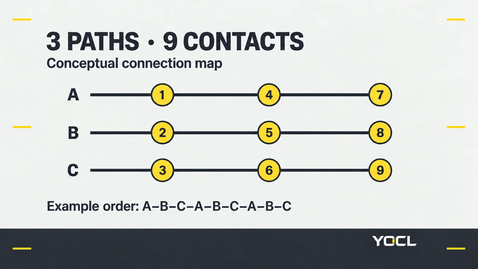
That repeating pattern is an example, not a rule for every three-pole product. The exact drawing must establish the actual sequence. Likewise, a 4P label alone does not tell you which contact is neutral, or whether the arrangement suits the intended devices. Record the assigned circuit function at each position before evaluating a match.
A multi-pole comb also does not mechanically link breaker handles or establish their switching behaviour. Those functions belong to the protective device and its documented arrangement.
Matching Pitch or Sharing a DIN Rail Is Only Part of Fit
Tooth pitch is measured between corresponding points on successive contacts. Compare it with the actual terminal positions along the proposed row. Side-mounted accessories, gaps and different device widths can change that row; overall length alone cannot establish the contact pattern.
Mechanical engagement needs more than that horizontal spacing. Check contact width and thickness, the opening where applicable, projection and terminal height against the exact receiving-device drawing. Also confirm which connection side and terminal position are intended for the comb. A partly engaged contact is not a documented fit.
Electrical matching is a separate question: each tooth must reach the intended circuit function. A geometrically aligned comb can still have the wrong pole sequence for the device row.
The DIN-rail profile and accessory guide covers mechanical mounting. Sharing that mounting rail does not establish matching busbar contacts. Similarly, a terminal-block bridge is an accessory for its specified terminal system; the terminal-block connection guide explains that different commoning arrangement.
A Catalogue Current Value Is Not a Complete Assembly Rating
YOCL’s BS101-2 entry pairs 10 mm² copper cross-section with 63 A catalogue current capacity. Both fields belong to that complete model row. They are manufacturer declarations, not an independent test presented in this article, and they must not be transferred to every pin comb or interpreted as 63 A available separately at each tooth.
Current suitability depends on the documented product and supply arrangement, the proposed loading and the applicable operating conditions. A normal-current entry also does not establish short-circuit withstand or fault-protection performance. Obtain the relevant evidence for the completed equipment rather than calculate a rating from tooth count.
At assembly level, the public abstract of IEC 61439-1:2020 covers construction, technical characteristics and verification for low-voltage switchgear and controlgear assemblies, used with the relevant assembly-specific part. IEC 61439-3:2024 addresses distribution boards intended to be operated by ordinary persons within its defined scope. These are assembly references; citing them does not certify an individual YOCL comb.
In the distinct U.S. panelboard context, the UL Solutions Panelboard Application Guide discusses identified field-installed units and specified busbar kits for applicable panelboards. It also explains why different manufacturers’ or styles’ units may not be interchangeable. This supports checking the actual equipment identification, rather than treating apparent fit as approval.
Choose the Next Document by the Question Still Open
| Remaining question | Next document or resource | Information to carry forward |
|---|---|---|
| Does this pin, fork or U contact fit? | Exact comb drawing and receiving-device terminal instructions | Model codes, contact profile, dimensions and connection side |
| Which teeth are electrically common? | Model circuit/connection drawing and device-row schedule | Pole sequence and assigned function at each position |
| Will the contacts align along the row? | Dimensioned device layout and comb drawing | Terminal centres, auxiliary-device gaps and required contact count |
| Does the arrangement meet the electrical duty? | Product rating conditions and equipment verification records | Current, voltage, supply location, operating conditions and fault duty |
| Can the comb be cut, and what covers are required? | Model-specific instructions and accessory schedule | Approved length treatment, end caps, unused-contact protection and feed connection |
These routes also help distinguish neighbouring accessories. A power distribution block connects incoming and outgoing conductors through designated connection positions. A busbar support insulator holds a conductor and provides insulating separation from its support. Neither is another name for the repeated terminal contacts of a comb.
For a YOCL enquiry, use the comb-busbar range linked above and send the exact device model, contact drawing, pole sequence, connection count and known electrical duty. That gives the interface and supporting documents a clear basis for review.
References
- YOCL ELECTRIC — BS101 Series 1P Pin MCB Busbars: first-party interface and BS101-2 catalogue data.
- YOCL ELECTRIC — BS201 Series 1P C45 Fork MCB Busbars: first-party series designation, exterior image and drawing.
- YOCL ELECTRIC — BS301 Series 1P U-Type MCB Busbars: first-party U-type designation and exterior contact reference.
- YOCL ELECTRIC — Comb Busbar Manufacturer: first-party range and pole/contact/layout distinctions.
- IEC — IEC 61439-1:2020: public abstract only; general assembly and verification scope.
- IEC — IEC 61439-3:2024: public abstract only; distribution-board scope.
- UL Solutions — Panelboard Application Guide: Field-installed units or equipment section; scoped identification and interchangeability guidance.