
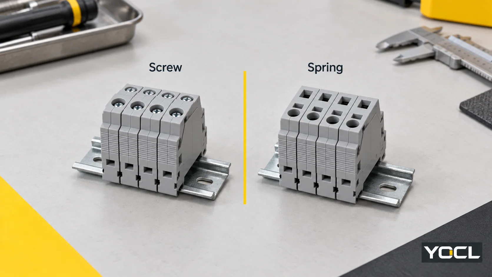
Choose screw terminal blocks when a documented tightening process fits your assembly and service practice. Choose spring terminal blocks when removing the conductor-clamp torque-setting step suits your workflow, after confirming wire preparation and operation. Direct push-in is one spring design. Neither connection label establishes an inspection interval.
This comparison concerns modular DIN rail terminals for copper conductors. Compare candidates with the same circuit function, suitable electrical ratings and service conditions. For the wider map of terminal functions and mounting forms, use the terminal-block guide.
Wiring tradeoffs: where the work goes
The useful comparison is the complete termination and rework process, including wire preparation and access.
| Comparison point | Screw terminal | Spring terminal |
|---|---|---|
| Conductor-clamp operation | A screw establishes the connection; obtain the prescribed tightening value and tool requirements | Entry requires clamp opening or permits direct push-in, depending on design |
| Wire eligibility | Confirm conductor type, size and permitted preparation | Confirm those same fields; the spring label does not settle them |
| Access during rework | Allow access to the tightening screw and conductor entry | Allow access to the opening/release feature and conductor entry |
| Workflow to compare | Preparation, insertion, tightening, documented checks and removal | Preparation, opening/insertion, documented checks and release |
Screw-type connections can transmit pressure through an intermediate clamping part. Do not assume that every screw tip bears directly on the wire. The International Electrotechnical Commission (IEC) distinguishes direct and indirect screw action in its terminology. IEC 60999-1 public preview, Section 3.
For a fair assembly comparison, use the same conductor and repeat the actual workshop preparation and acceptance process for each eligible model. A quick insertion demonstration does not measure ferrule preparation, tightening control or later conductor removal. Without matched measurements, a percentage claim about wiring speed adds little to the decision.
Spring clamp and push-in describe different things
Spring clamp describes the clamping mechanism; push-in describes an entry action. Spring designs can be opened with a tool, operated through an actuator or used by direct insertion. IEC 60352-7 illustrates these different arrangements. IEC 60352-7:2026 public preview, Figure 1.
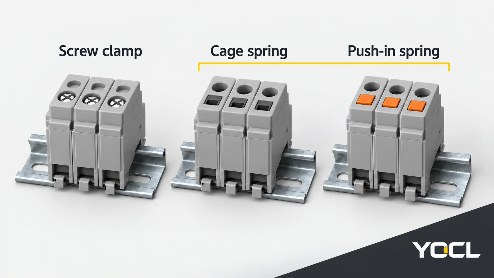
Direct insertion does not establish tool-free removal. Verify release access with the surrounding wiring and accessories installed.
Conductor preparation can change the choice
Conductor acceptance is a separate specification from clamp type. IEC 60947-7-1 classifies terminal blocks by accepted conductor forms and preparation capability, and distinguishes a rated cross-section from a connecting-capacity range. IEC 60947-7-1:2025 public preview, Sections 3–4.
A solid end, a bare stranded end and a ferruled end present different termination conditions. Check the exact block’s information for your conductor type, size, preparation and conductor count. A ferrule does not automatically make every terminal suitable for that wire. The wire-ferrule guide explains the prepared-end compatibility question in more detail.
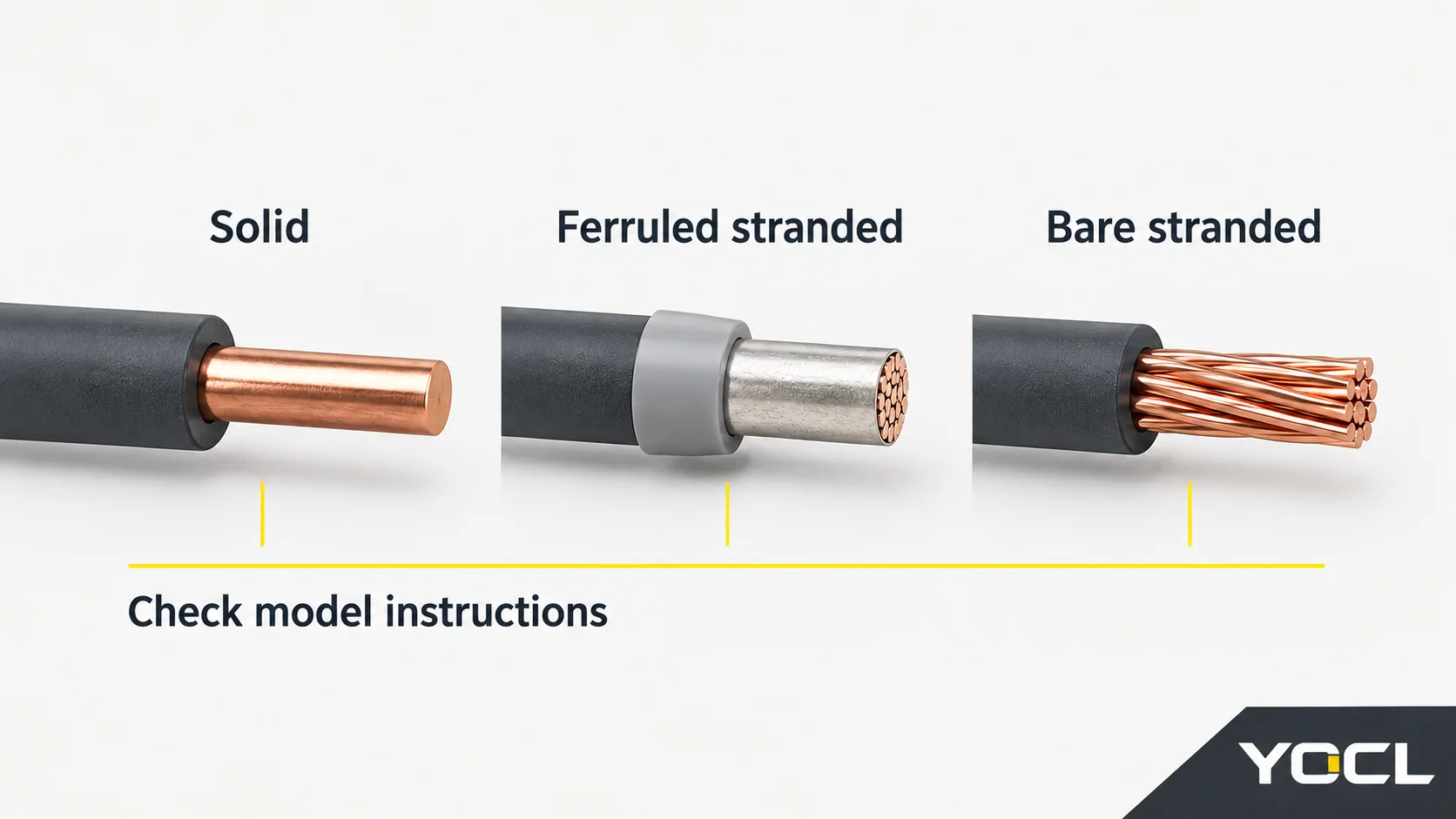
YOCL lists UK screw, SJ cage-spring and PT push-in ranges. Their public model information demonstrates why a similar size designation is insufficient for substitution.
| Example and source | Publicly declared field | What it leaves to confirm |
|---|---|---|
| UK-2.5B in the UK screw range | The row identifies an M3 screw but does not give a conductor range | Accepted conductor/preparation range and tightening torque; M3 is a screw size, not a torque |
| SJ-2.5 in the cage-spring range | Rigid conductors: 0.2–4 mm²; flexible conductors: 0.2–2.5 mm² | Preparation-specific acceptance and opening/release instructions |
| PT2.5 in the PT push-in range | Rated cross-section: 2.5 mm²; the series describes direct insertion of suitable solid or ferruled conductors | Complete accepted ranges for the selected prepared end and release method |
These are first-party catalogue fields, not a matched performance test. The flexible-conductor range given for SJ-2.5 cannot be transferred to PT2.5. Request the missing model information before treating either as a replacement for an existing terminal.
Maintenance: separate tightening from inspection
For a screw terminal, the installation process needs the prescribed tightening instructions. Its maintenance policy must separately state whether and when retightening is required. Obtain that policy for the exact terminal and equipment; do not invent an annual interval from the connection name.
A spring conductor clamp removes the user-set tightening operation at that contact. It does not remove the need to investigate damaged parts, deteriorating wiring or an unsuitable connection. If a supplier calls a terminal “maintenance-free,” ask which task that statement excludes and which inspections remain in the equipment maintenance plan.
As an example of wider maintenance guidance, Great Britain’s Health and Safety Executive calls for maintenance to prevent danger and competent inspection/testing of fixed installations. Its general equipment guidance identifies damaged connectors, insecure cables and burn marks as reasons for action. It supplies no DIN-terminal retightening interval. HSE, Introduction to electrical safety.
For either mechanism, arrange any connection work under the equipment’s isolation and service instructions. A suspected damaged contact needs competent assessment; changing the clamping technology does not establish that the underlying problem has been resolved.
Which tradeoff fits your panel?
| Your situation | Candidate decision | Condition that makes the decision defensible |
|---|---|---|
| Established screw design, controlled tightening tools and accessible terminals | Retain or select screw terminals | The exact conductor and service instructions fit; the present process has a clear acceptance method |
| Repeated assembly using one confirmed prepared end | Consider a suitable direct push-in spring terminal | Evaluate the whole preparation/insertion/release process, not insertion alone |
| Field wiring brings different conductor forms | Either a compatible screw or an opened-spring design may fit | Verify every expected wire form; do not infer direct-insertion eligibility from the spring label |
| Different circuits have different service needs | Both mechanisms may belong in the panel | Qualify each connection and keep its instructions identifiable |
| The choice is being justified by vibration, heating or reliability alone | Neither label decides | Obtain application-specific declarations or matched evidence for the exact candidates |
For a change of series, also verify the footprint, rail fit, end plates, bridges and markers. Shared DIN mounting does not establish accessory interchangeability. Keep screw or release access usable during the intended service task.
Use the YOCL terminal-block range to identify candidates. Provide the conductor types and prepared ends, circuit function, required ratings and access constraints, then request the matching connection and maintenance documents. That turns a mechanism preference into a reviewable terminal choice.
References
- IEC, IEC 60999-1:1999 — public preview, Section 3, screw and screwless clamping terminology.
- IEC, IEC 60352-7:2026 — public preview, Section 3 and Figure 1, spring-clamp terminology and operation.
- IEC, IEC 60947-7-1:2025 — public preview, Sections 3–4, terminal-block definitions and classification. Only cited public preview sections were consulted; these references do not establish YOCL certification.
- YOCL ELECTRIC, UK Series Screw DIN Rail Terminal Blocks, UK-2.5B catalogue row.
- YOCL ELECTRIC, SJ Cage Spring DIN Rail Terminal Blocks, SJ-2.5 catalogue row.
- YOCL ELECTRIC, PT Series Push-In DIN Rail Terminal Blocks, PT2.5 row and series operation description. First-party pages checked 11 October 2026.
- Health and Safety Executive, Great Britain, Introduction to electrical safety, Maintenance and Fixed installations.