
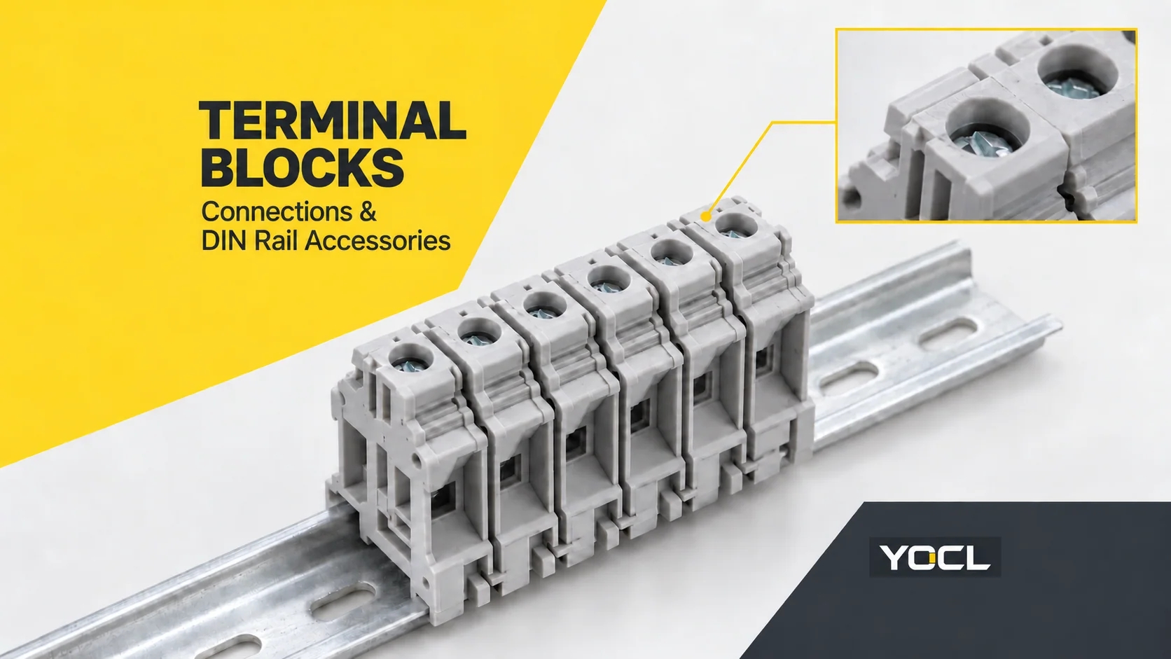
A terminal block is a supported wiring connection that secures conductors and separates connections where insulation is required. In a control cabinet, a familiar form is a modular DIN-rail block: wires connect through its clamping points, while the rail supports the assembly. The block’s circuit configuration determines which points are connected.
This guide uses a grey, single-level DIN-rail feed-through terminal as its representative form, based on YOCL’s UK screw-terminal range. “Terminal block” also describes other shapes; choosing one clear example helps explain the connection without confusing it with a distribution block or circuit-board connector.
What a terminal block connects—and what stays separate
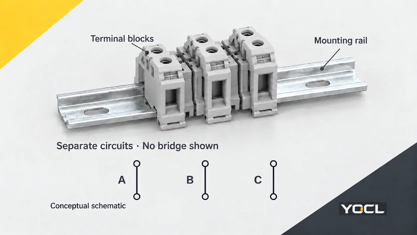
A feed-through terminal provides a connection between its designated conductor points. Several blocks can sit side by side, but adjacent ordinary feed-through blocks are not electrically joined just because they share a rail. Commoning selected circuits requires the specified bridge or other documented connection arrangement.
The housing supports and separates connections. The scope of UL 1059: Terminal Blocks describes supported wiring connections and the required insulation between terminations and mounting surfaces. Protective-conductor terminals are a distinct case within that scope.
The DIN rail is the mounting support. Do not treat it as a supply busbar. Protective-earth terminal systems can have a designated electrical connection to their mounting support, but that function must be established by the relevant product and installation requirements. IEC 60715:2017 covers compatible mechanical rail mounting and explicitly leaves the rail’s protective-earthing function to the relevant product standard.
A standard feed-through block also does not switch or protect the circuit. Disconnect and fuse-terminal configurations add specific functions; their names and diagrams must be checked separately.
Separate the mounting form, connection method and circuit function
These descriptions answer different questions about the same component:
| Question | Examples | What you need to identify |
|---|---|---|
| Where is it mounted? | DIN rail; panel-mounted strip; printed circuit board | Mounting profile or footprint, available space and physical form |
| How is the conductor held? | Screw clamp; cage spring; push-in spring | Accepted conductor preparation and the model’s connection instructions |
| Which points are connected? | Feed-through; multi-level; protective earth; disconnect or fuse configuration | The circuit diagram and function of each connection point |
For example, “DIN-rail screw-clamp feed-through terminal” identifies all three. “DIN rail” alone says nothing about whether the conductor is held by a screw or spring.
Terminal strips and barrier blocks group connections in a different physical arrangement. Board-mounted terminals connect to a printed circuit board, while pluggable designs introduce a mating connector interface. These are broader terminology distinctions, not alternative names for the chosen DIN-rail form. Wikipedia’s screw-terminal overview describes strip/barrier and board-mounted forms.
Screw, cage-spring and push-in connections
Screw-clamp terminals
A screw-operated clamp secures the conductor. YOCL’s UK screw DIN-rail terminal blocks use PA66 insulating housings and declared brass conductive components, with feed-through, compact, multi-level and protective-earth configurations across the range.
Select against the exact conductor range and preparation requirements. The screw size, tightening instruction and accessory fit belong to the chosen model; the family name does not supply a universal tightening torque.
Cage-spring terminals
A spring-clamp design uses spring force to retain the conductor. YOCL’s SJ cage-spring range lists individual rigid and flexible conductor ranges and supports TH35-7.5 or TH35-15 rails.
Check the model’s method for opening, inserting and releasing the conductor. “Spring connection” does not mean every design operates identically or accepts every flexible conductor without preparation.
Push-in terminals
Push-in is a spring-based connection design in which an eligible conductor can be inserted directly. YOCL’s PT push-in range describes insertion for suitable solid conductors or conductors fitted with ferrules; a spring retains the conductor, and a release mechanism permits removal.
Direct insertion depends on the accepted conductor and its preparation. Do not generalize it to every bare fine-stranded wire, or assume insertion and release both require no tool.
| Connection description | Relevant comparison | Evidence to check |
|---|---|---|
| Screw clamp | Screw-operated conductor retention | Conductor type/range, preparation and tightening instructions |
| Cage spring | Spring retention and the model’s actuation method | Conductor type/range and opening/release instructions |
| Push-in spring | Direct insertion of eligible prepared conductors | Solid/ferruled acceptance, range and release instructions |
The useful comparison is the documented connection process, not a blanket claim that one technology is always better.
Circuit configurations change the job of the block
- Feed-through: connects the designated points through one terminal circuit.
- Multi-level: stacks connection levels to organize more circuits within a footprint. Check the diagram before assuming the levels are joined.
- Protective earth (PE): provides a designated protective-conductor connection. YOCL identifies yellow-green USLKG variants in its UK range; colour alone is not evidence that an ordinary block bonds to the rail.
- Disconnect or fuse terminal: adds a separation or fuse-related function. Its electrical arrangement and any fuse requirement must come from that model’s documentation.
These functions are independent of clamping technology. A spring terminal is not automatically a PE terminal, and a multi-level terminal is not automatically a distribution bus.
DIN rail accessories have different jobs
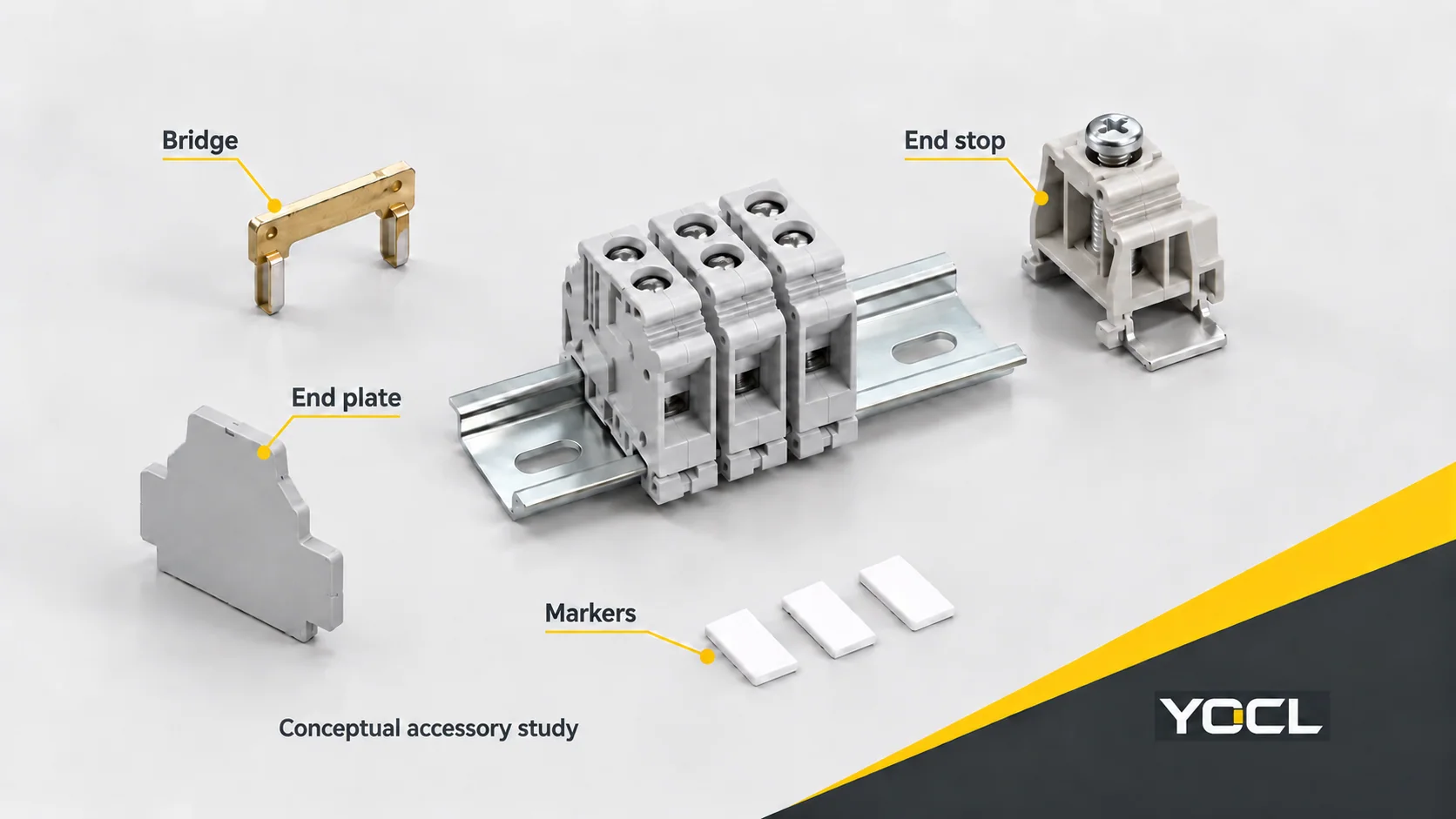
The accessories complete the terminal system; they are not interchangeable pieces of trim.
| Accessory | Main job | Compatibility question |
|---|---|---|
| Bridge or jumper | Electrically joins selected terminal points for potential distribution | Does its pitch, position and approved configuration match these terminals? |
| End plate or end cover | Closes an applicable open housing side | Does this terminal need a separate plate, and which profile fits? |
| End stop or end clamp | Restrains movement along the rail | Does it fit the rail profile and the assembly’s fixing requirements? |
| Partition plate | Provides the specified physical separation between groups | Is it the correct series part and arrangement? |
| Marker | Identifies terminals or circuits | Does it fit the marking location and identification schedule? |
An end plate insulates; an end stop retains. One does not replace the other. Likewise, a marker identifies a circuit but does not create an electrical connection.
YOCL’s UK record lists model-specific centre-type jumpers and end plates. It also states that enclosed-housing models including UK-35N require no separate end plate. That exception is why “add an end plate to every terminal” is not a reliable rule. The PT record lists compatible end covers, end stops, partitions, marking components and bridges; select them against the individual terminal model.
Matching appearance or mounting rail does not establish accessory interchangeability between different series.
Read conductor ranges by construction, not just the model name
YOCL’s published SJ-2.5 model data makes the distinction clear:
| SJ-2.5 catalogue field | Declared value |
|---|---|
| Rated cross-section | 2.5 mm² |
| Rigid conductor range | 0.2–4 mm² |
| Flexible conductor range | 0.2–2.5 mm² |
The rated cross-section is not a universal maximum for every conductor construction. The rigid-wire upper value must not be transferred to flexible wire. These are the manufacturer’s declared fields for this model, not an inferred approval for a ferruled conductor.
When a ferrule is used, verify that both the ferrule and receiving terminal accept the intended arrangement. What Is a Wire Ferrule? Types, Sizes and Terminal Compatibility explains that separate conductor-preparation task.
For standards evidence, IEC 60947-7-1:2025 covers industrial screw-type and screwless terminal blocks for copper conductors within its stated scope. Its fourth edition replaces the 2009 edition. The public abstract establishes the standard’s scope; it does not establish certification of a YOCL model. UL 1059 likewise states that meeting its requirements does not, by itself, assure suitability in an end product.
Choose the next document by the question still open
| Remaining question | Next resource |
|---|---|
| Which terminal family fits the panel concept? | YOCL terminal-block catalogue |
| Which DIN-rail connection method and configuration are available? | YOCL DIN-rail terminal-block range |
| Will this conductor or ferrule fit? | The exact terminal’s conductor/preparation data and the ferrule guide above |
| Which bridge, end plate or fixing part belongs in the assembly? | The model-specific accessory schedule and assembly instructions |
For an enquiry, send a terminal schedule with the conductor type and size, circuit function, current and voltage requirements, rail profile, quantity and accessory list. Those details let the requested model and its supporting evidence be confirmed together.
References
- YOCL ELECTRIC — UK Series Screw DIN Rail Terminal Blocks; first-party connection, configuration and accessory information.
- UL Standards & Engagement — UL 1059: Terminal Blocks, sixth edition, December 11, 2024; public scope only.
- IEC — IEC 60715:2017; public abstract on mechanical rail mounting and the separate protective-earthing standard boundary.
- Wikipedia — Screw terminal, Description, Applications and Multiway versions; general terminology only.
- YOCL ELECTRIC — SJ Cage Spring DIN Rail Terminal Blocks; first-party mounting and conductor-range data.
- YOCL ELECTRIC — PT Series Push-In DIN Rail Terminal Blocks; first-party connection and accessory information.
- IEC — IEC 60947-7-1:2025, fourth edition, April 15, 2025; public abstract only.