
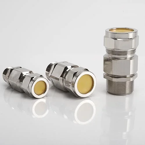
BDM-5 Explosion-Proof Armored Cable Gland
BDM-5 single-seal armored cable gland with compound barrier flameproof sealing for industrial hazardous-area cable entry.
- Brass, nickel-plated brass, SS304 or SS316 body options.
- IP66 protection; operating temperature −40 °C to +60 °C.
- Reversible armor rings and a multiple-layer seal.
- 22 sizes with metric threads from M16×1.5 to M110×1.5.
- Non-standard metric thread diameters and pitches available on request.
Overview
The YOCL ELECTRIC BDM-5 Explosion-Proof Armored Cable Gland is a single-seal type for armored cable, with compound barrier flameproof sealing. Its multiple-layer seal accommodates the cable ranges listed in the size table, while reversible armor rings support different armored cable constructions.
Body options include brass, nickel-plated brass, SS304 and SS316. The supplied specification lists Ex db, Ex eb and Ex tb marking for hazardous-area applications in Zones 1, 2, 21 and 22.
Features
- Compound barrier sealing: Flameproof barrier construction as described in the supplied specification.
- Multiple-layer seal: Cable sizes are selected using the model-specific inner and outer sheath dimensions.
- Reversible armor rings: Accommodate different armored cable constructions.
- Body material options: Brass, nickel-plated brass, SS304 and SS316.
- Thread selection: Standard metric entries and listed NPT/G nominal sizes, with non-standard metric thread options available on request.
Technical Specifications
| Parameter | Specification |
|---|---|
| Model | BDM-5 |
| Type | Single seal type for armored cable |
| Sealing construction | Compound barrier flameproof sealing; multiple-layer seal |
| Armor retention | Reversible armor rings |
| Operating temperature | −40 °C to +60 °C |
| Supplied Ex marking | Ex db IIC Gb; Ex eb IIC Gb; Ex tb IIIC Db |
| Ingress protection | IP66 |
| Body material options | Brass; nickel-plated brass; SS304; SS316 |
| Listed hazardous area applications | Zone 1; Zone 2; Zone 21; Zone 22 |
| Approvals stated in supplied specification | CNEx; CCC; EAC (CUTR) |
| Standards listed in supplied specification | GB 3836.1; GB 3836.2; GB 3836.3; GB 12476.1; GB 12476.5 |
| Standard metric thread pitch | 1.5 mm, as listed in the size table |
| Non-standard metric threads | Diameters and pitches listed below; available on request |
The supplied approval statements do not include certificate numbers or the editions of the listed standards.
Dimension
Cable Selection Data
Dimensions are in millimetres, except the NPT/G nominal thread sizes in inches. A and B retain the supplied table’s inner sheath and outer sheath labels.
| Size | Metric entry thread AG | NPT/G nominal size (inch) | Inner sheath A (mm) | Outer sheath B (mm) |
|---|---|---|---|---|
| 16 | M16×1.5 | — | 8 | 7–15 |
| 20B | M20×1.5 | 1/2 | 10 | 7–15 |
| 20C | M20×1.5 | 1/2 | 15 | 10–20 |
| 25B | M25×1.5 | 3/4 | 15 | 10–20 |
| 25C | M25×1.5 | 3/4 | 20 | 12–26.5 |
| 32B | M32×1.5 | 1 | 20 | 12–26.6 |
| 32C | M32×1.5 | 1 | 27 | 19–33 |
| 40B | M40×1.5 | 1-1/4 | 27 | 19–33 |
| 40C | M40×1.5 | 1-1/4 | 31 | 22–40 |
| 50B | M50×1.5 | 1-1/2 | 31 | 22–40 |
| 50C | M50×1.5 | 1-1/2 | 41 | 29–50 |
| 63B | M63×1.5 | 2 | 41 | 29–50 |
| 63C | M63×1.5 | 2 | 55 | 35–63 |
| 75B | M75×1.5 | 2-1/2 | 55 | 35–63 |
| 75C | M75×1.5 | 2-1/2 | 65 | 45–76 |
| 85B | M85×1.5 | 3 | 65 | 45–76 |
| 85C | M85×1.5 | 3 | 65 | 61–90 |
| 90B | M90×1.5 | 3-1/2 | 65 | 45–76 |
| 90C | M90×1.5 | 3-1/2 | 75 | 61–90 |
| 100B | M100×1.5 | 4 | 75 | 61–90 |
| 100C | M100×1.5 | 4 | 90 | 61–103 |
| 110 | M110×1.5 | 4 | 90 | 61–103 |
A is a single dimension in the supplied table, rather than a stated clamping range. The drawing shows A at the entry-side internal opening. A dash indicates that no NPT/G thread size was supplied for that row; specify NPT or BSP (G) explicitly when ordering.
External Dimensions
| Size | Maximum size D (mm) | Body length L1 (mm) | Entry thread length L (mm) |
|---|---|---|---|
| 16 | 27 | 53 | 15 |
| 20B | 27 | 53 | 15 |
| 20C | 33 | 53 | 15 |
| 25B | 33 | 53 | 15 |
| 25C | 39 | 54 | 15 |
| 32B | 39 | 54 | 17 |
| 32C | 50 | 54 | 17 |
| 40B | 50 | 54 | 19 |
| 40C | 60 | 65 | 19 |
| 50B | 60 | 65 | 19 |
| 50C | 73 | 68 | 19 |
| 63B | 73 | 68 | 20 |
| 63C | 89 | 79 | 20 |
| 75B | 89 | 79 | 22 |
| 75C | 99 | 79 | 22 |
| 85B | 99 | 79 | 22 |
| 85C | 99 | 79 | 22 |
| 90B | 99 | 79 | 23 |
| 90C | 115 | 86 | 23 |
| 100B | 115 | 86 | 24 |
| 100C | 129 | 86 | 24 |
| 110 | 129 | 86 | 24 |
L1 is the body length beyond the entry thread; L is the entry thread length, following the source drawing.
Custom Metric Threads
The following non-standard thread diameters and pitches are available on request. Where more than one pitch is listed, specify one pitch for the order. The standard size table does not assign separate cable ranges or external dimensions to these custom threads.
| Nominal thread diameter | Available pitch (mm) |
|---|---|
| M18 | 1.5 |
| M22 | 1.5 |
| M24 | 1.5 |
| M27 | 1.5 / 2.0 |
| M28 | 1.5 |
| M30 | 1.5 / 2.0 |
| M36 | 1.5 / 2.0 |
| M40 | 2.0 |
| M48 | 2.0 |
| M50 | 2.0 |
| M60 | 1.5 / 2.0 |
| M63 | 2.0 |
| M64 | 1.5 / 2.0 |
| M72 | 1.5 / 2.0 |
| M75 | 2.0 |
| M80 | 1.5 / 2.0 |
| M85 | 2.0 / 3.0 |
| M90 | 2.0 |
| M100 | 2.0 |
| M110 | 2.0 |
| M115 | 1.5 |
| M120 | 1.5 / 2.0 |
Ordering Information
Specify BDM-5 size, body material, entry thread standard, diameter and pitch, cable inner and outer sheath dimensions, and armor construction. For custom threads, include the enclosure entry specification and required thread engagement.
Specify the compatible compound barrier configuration with the order. Compound formulation, curing requirements and accessory supply are not defined in the supplied data and should follow the documentation for the delivered configuration.