

LP-24 Quick-Lock Waterproof Circular Connectors
YOCL ELECTRIC LP-24 Quick-Lock Waterproof Circular Connectors provide detachable power and signal interfaces with 2–6 contacts.
- Contact-dependent current and conductor configurations, including 2.5–4.0 mm² and 6.0–8.0 mm² conductor sections.
- Pushbutton snap lock supports single-hand mating and release.
- Screw clamp termination and IP68 in the connected state.
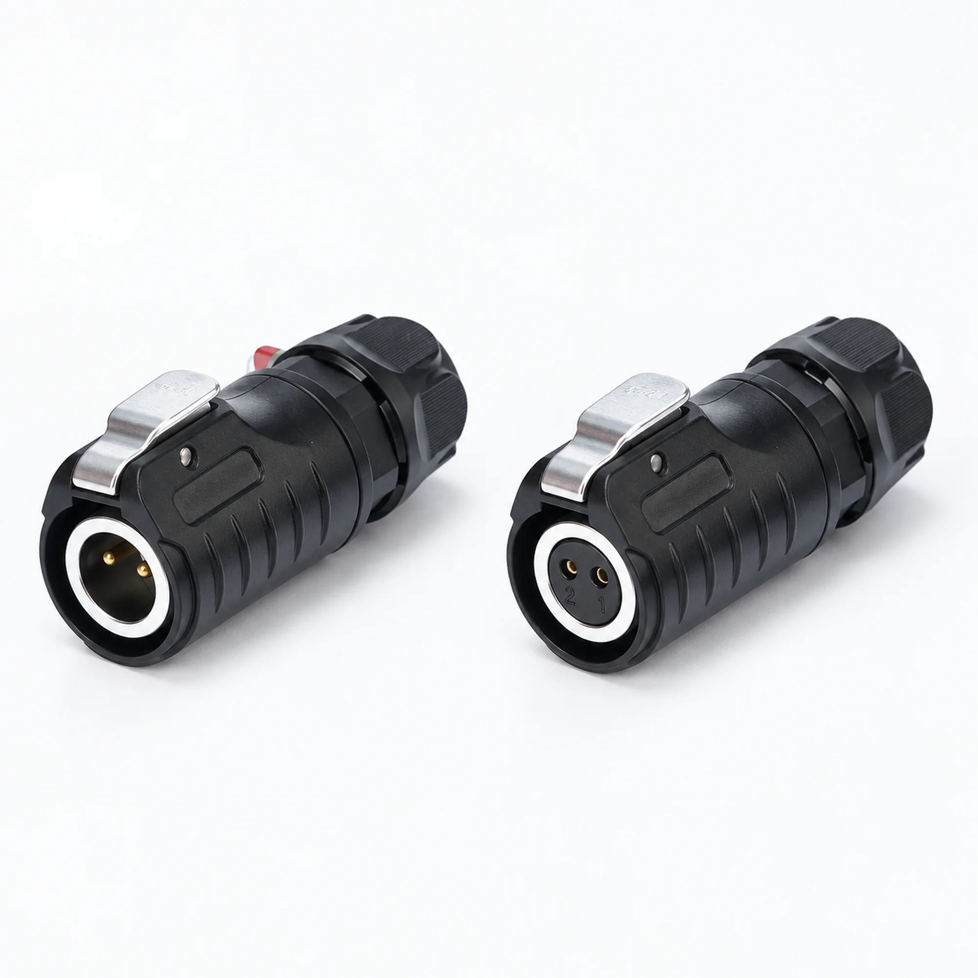
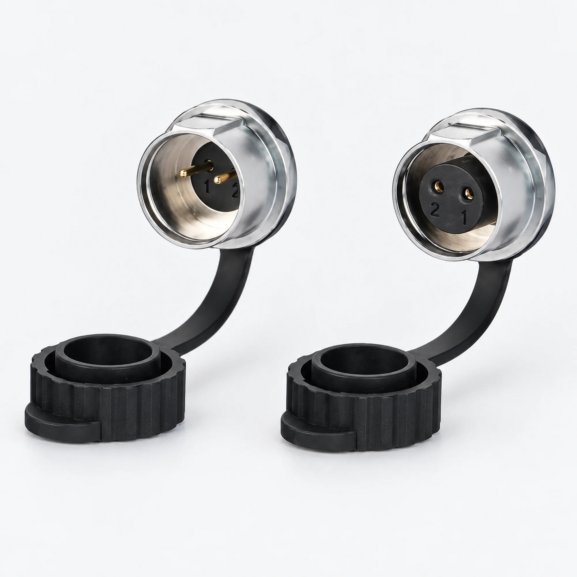
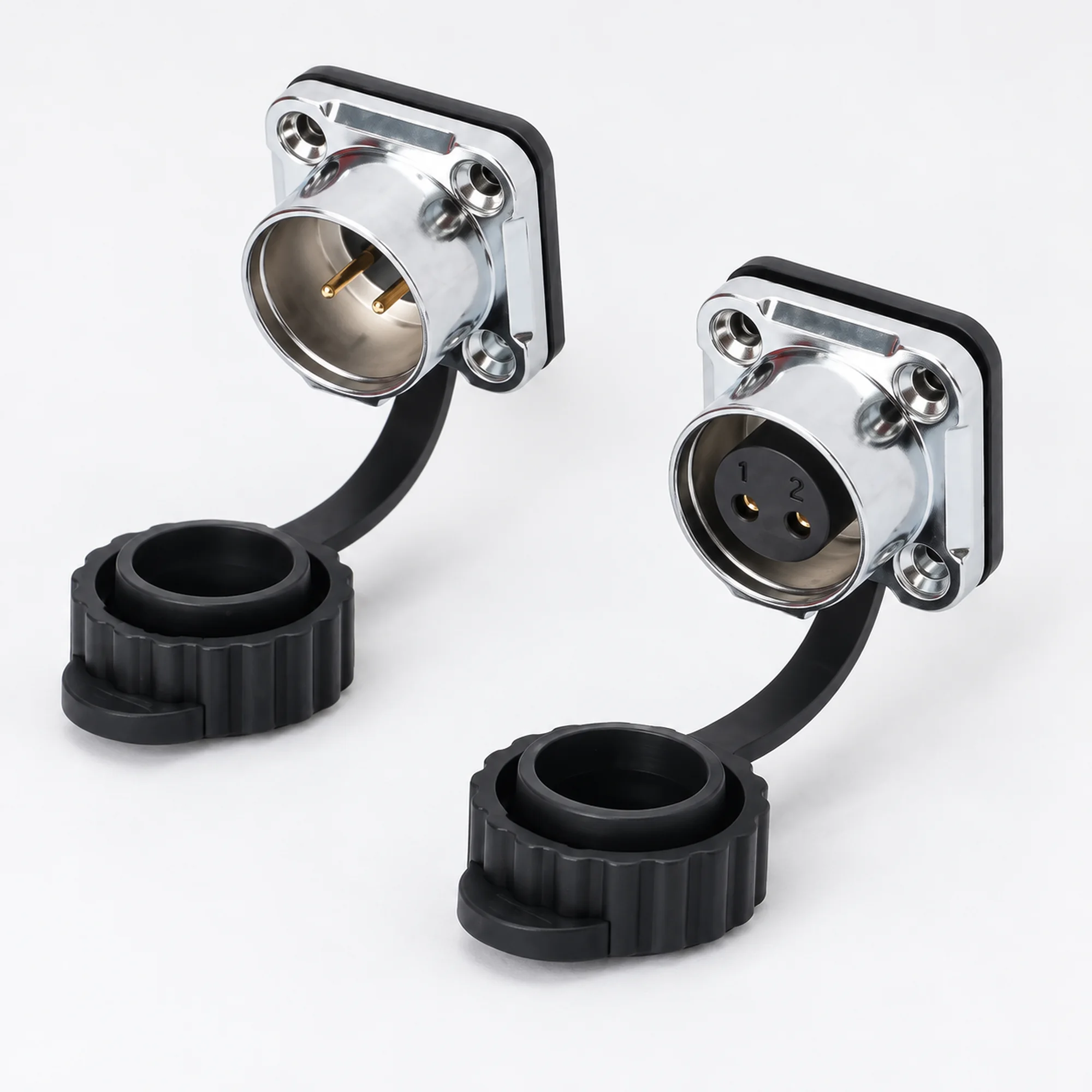
- Cable plugs, inline docking sockets, single-hole panel sockets and four-hole flange sockets, with male and female electrical contacts.
- Cable diameter options: Ø5–7 / Ø7–10.5 / Ø10.5–14 mm.
Overview
YOCL ELECTRIC LP-24 Quick-Lock Waterproof Circular Connectors provide detachable electrical interfaces with 2, 3, 4, 5 or 6 contacts. The series lists conductor configurations from 2.5–4.0 mm² to 6.0–8.0 mm², with current ratings paired to the selected contact group and wiring configuration.
A pushbutton snap lock supports single-hand mating and release. Screw clamp terminals connect the conductors, and cable plugs, inline docking sockets and two panel socket formats are listed with male and female contact options. The catalogue specifies IP68 protection in the connected state.
Features
- Pushbutton snap lock: Supports single-hand mating and release.
- IP68 in the connected state: Protection applies to the mated connector assembly.
- Cable and panel formats: Cable plugs, inline docking sockets, single-hole panel sockets and four-hole flange sockets are listed.
- Male and female contacts: Choose electrical contact gender for each side of the connection.
- Screw clamp termination: Conductors are secured with a screw-operated connection.
- Plated copper-alloy contacts: Gold plating over a nickel underplate is specified.
Technical Specifications
| Parameter | Specification |
|---|---|
| Brand | YOCL ELECTRIC |
| Series | LP-24 |
| Connector type | Quick-lock waterproof circular connector |
| Contact counts | 2 / 3 / 4 / 5 / 6 |
| Locking method | Pushbutton snap lock |
| Wire termination | Screw clamp |
| Contact gender | Male / female |
| Connector formats | Cable plug; inline docking socket; single-hole panel socket; four-hole flange socket |
| Ingress protection | IP68 in the connected state |
| Contact material | Copper alloy |
| Contact finish | Gold plating over nickel underplate |
| Insulator | Engineering plastic |
| Housing construction | Engineering plastic / metal, depending on configuration |
| Metal housing surface finish | Chrome plating |
Current and Conductor Configurations
| Contact group | Listed current | Conductor section | Catalogue AWG entry |
|---|---|---|---|
| 2 / 3 / 4 | 25 A | 2.5–4.0 mm² | 14–12 AWG |
| 2 / 3 / 4 | 30 A | 6.0–8.0 mm² | 10–8 AWG |
| 5 / 6 | 10 A | 2.5–4.0 mm² | 14–12 AWG |
| 5 / 6 | 10 A | 6.0–8.0 mm² | 10–8 AWG |
Multiple conductor configurations are listed within each contact group. The ordering codes below do not identify which configuration is supplied. Specify the required current, voltage and conductor section together when ordering. No rated voltage is assigned in this table. Metric conductor sections and AWG entries are retained as catalogue data.
Cable Outer Diameter Options
| Selection | Listed options |
|---|---|
| Cable jacket diameter | Ø5.0–7.0 / Ø7.0–10.5 / Ø10.5–14.0 mm |
Cable jacket diameter and conductor cross-section are separate selection criteria. The diameter ranges are series-level options and are not assigned to individual contact counts.
Dimension
| Dimension | Value |
|---|---|
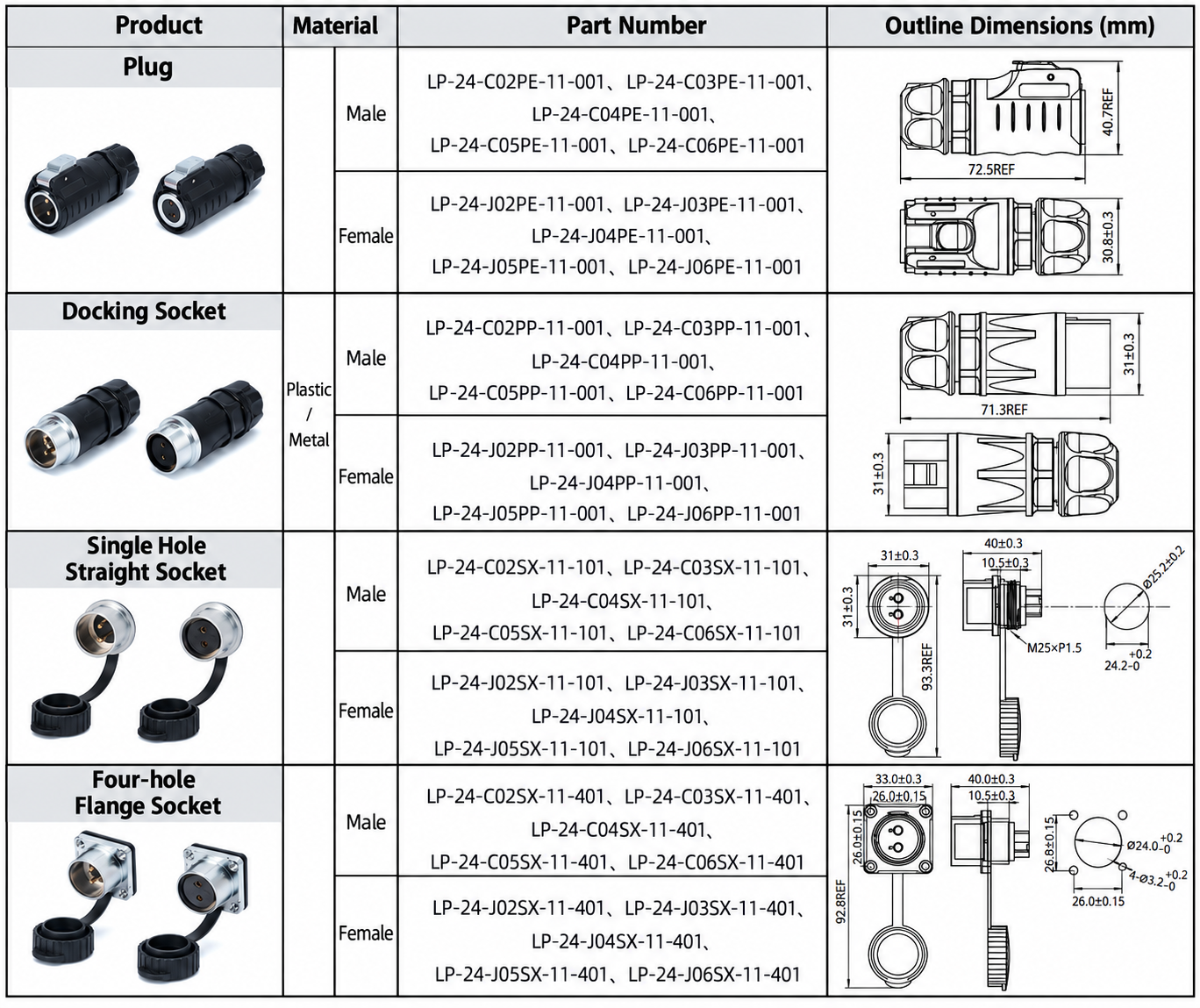
| Cable plug length, REF | 72.5 mm |
| Inline socket length, REF | 71.3 mm |
| Single-hole socket mounting thread | M25 × 1.5 |
| Flange body horizontal width | 33.0 ± 0.3 mm |
| Flange body hole pitch | 26.0 ± 0.15 mm |
REF identifies reference lengths in the drawings. Flange dimensions describe the connector body. Use the selected socket’s installation drawing for panel cutouts and their tolerances.
Connector Formats
| Format | Arrangement |
|---|---|
| Cable plug | Cable-terminated mating connector |
| Inline docking socket | Cable-terminated socket for an inline connection |
| Single-hole panel socket | Equipment socket mounted through one panel opening |
| Four-hole flange socket | Equipment socket with a four-hole mounting flange |
Male and female refer to the electrical contact gender. Specify connector format and contact gender separately when selecting a mating pair.
Ordering Code Guide
The catalogue lists 40 part numbers for LP-24. Replace nn in the following patterns with 02 / 03 / 04 / 05 / 06. The letters nn are a contact-count placeholder, not an orderable code. Add the LP-24- prefix to each pattern.
| Format | Contact gender | Code following the series prefix |
|---|---|---|
| Cable plug | Male | CnnPE-11-001 |
| Cable plug | Female | JnnPE-11-001 |
| Inline docking socket | Male | CnnPP-11-001 |
| Inline docking socket | Female | JnnPP-11-001 |
| Single-hole panel socket | Male | CnnSX-11-101 |
| Single-hole panel socket | Female | JnnSX-11-101 |
| Four-hole flange socket | Male | CnnSX-11-401 |
| Four-hole flange socket | Female | JnnSX-11-401 |
Examples of listed part numbers:
- LP-24-C02PE-11-001: Two contacts, male cable plug.
- LP-24-J06PE-11-001: Six contacts, female cable plug.
- LP-24-C03PP-11-001: Three contacts, male inline docking socket.
- LP-24-J04SX-11-101: Four contacts, female single-hole panel socket.
- LP-24-J06SX-11-401: Six contacts, female four-hole flange socket.
Both panel formats use SX. The final suffix 101 identifies a single-hole socket; 401 identifies a flange socket. The code identifies contact count, format and electrical contact gender. Include the electrical configuration and cable diameter separately in the enquiry.
Selection Guide
- Select the required contact count.
- Choose the connector format and electrical contact gender for each side of the mating pair.
- Match the conductor section and cable jacket diameter to the selected configuration.
- Obtain the applicable voltage rating and current/conductor configuration for the selected part number; the code alone does not distinguish the paired configurations.
- Use the selected socket’s drawing for panel layout. IP68 applies to the connected assembly.
Applications
- Detachable equipment power connections.
- Multi-contact signal interfaces.
- Cable-to-cable electrical connections.
- Panel-mounted equipment connections.
Ordering Information
Specify YOCL ELECTRIC, the complete LP-24 part number, contact count, connector format, contact gender, required current and voltage, conductor section, cable jacket diameter and quantity. For a mating pair, list both part numbers and their quantities.