
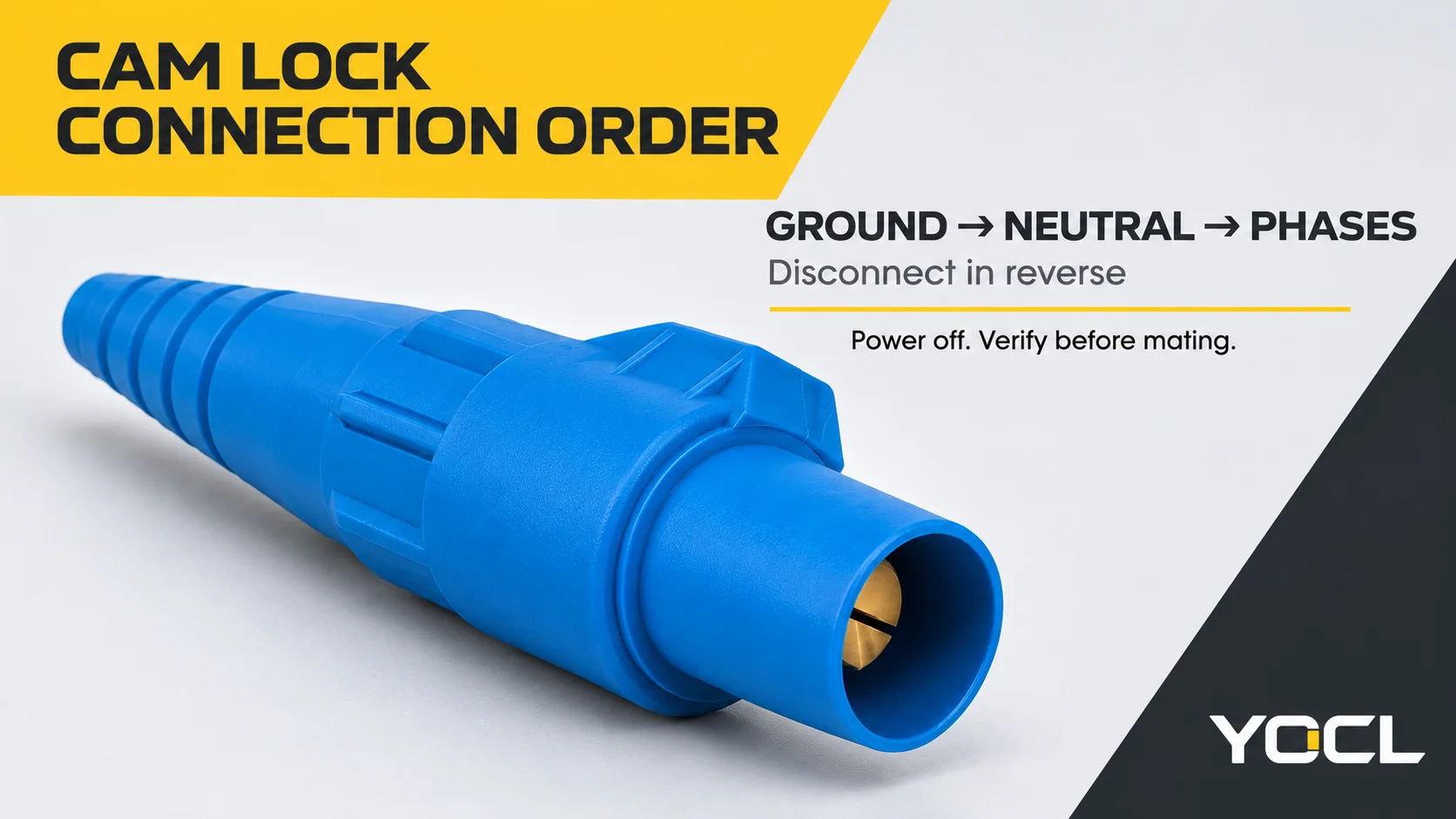
For a deenergized cam lock connection, connect ground first, neutral second where used, and phases last. Disconnect in the reverse order. Only qualified persons should carry out this work, after isolation and absence-of-voltage verification, under the equipment manual and site procedure.
| Connecting | Conductor function |
|---|---|
| First | Equipment grounding conductor |
| Next | Neutral, where the system uses one |
| Last | Phase conductors |
| Disconnecting | Conductor function |
|---|---|
| First | All phase conductors |
| Next | Neutral, where used |
| Last | Equipment grounding conductor |
With separately mated single-pole connectors, one action does not establish every required circuit connection. The sequence protects the intermediate states; it does not make live mating safe. Trystar’s docking-station manual and the Quick Connect Switch instructions hosted by Connecticut Electric specify the same ground-neutral-phase connection order. [1, 2]
Why order is the safety device on single-pole connectors
A single-pole cam lock connects one conductor. Ground, neutral and each phase have separate mating points. A person can connect a phase while leaving ground or neutral absent. One correctly matched connector cannot establish that the others are ready.
This is a different problem from matching a multipole plug, where the required contacts belong to one coordinated interface. The industrial plugs and sockets overview places these families in context. For the separate mechanical coding system, see industrial plug clock positions and colour codes. IEC 60309 clock-position coding is not a cam lock conductor-connection sequence.
Some assemblies enforce a sequence through interlocking. Loose individual connectors do not necessarily have that protection. Without a sequence interlock, the work procedure must control the order; human discipline does not become equivalent to a physical interlock or replace isolation.
There is a specific code context behind the rule. Mark C. Ode’s 2009 Electrical Contractor article describes NEC Article 520 applications and listed sequential-interlocking connectors: equipment ground first, grounded conductor next where used, then ungrounded conductors, with reverse disconnection. It also discusses other permitted protective arrangements. This dated commentary explains that application, not a universal legal rule for every cam lock installation. The adopted code and equipment instructions govern the actual project. [3]
Ground first, ground last
The equipment grounding conductor provides the intended fault-current path if a phase conductor faults to exposed conductive equipment. Establishing that path before any phase is connected avoids an intermediate state in which a phase connection exists but the intended protective connection does not.
During removal, the same dependency runs backward. As long as any phase remains connected, the equipment grounding connection remains in place. Removing ground first would remove that protective path while a phase connection still existed. This is the meaning of first make, last break in the sequence. It describes the order of separate conductor connections, not a claim that every individual cam lock has an automatically sequenced earth contact.
Ground and neutral have different jobs. The grounding conductor is not a substitute load-return conductor, and connecting it does not establish that the neutral is sound. Equally, a connected neutral does not replace equipment grounding. Their separate positions in the sequence reflect those different functions. [3]
Neutral second — and the open-neutral failure
Neutral comes before the phases because line-to-neutral loads need their intended reference and return path established before phase connections are completed. It stays until after every phase is disconnected.
In a three-phase four-wire system, or a split-phase system supplying line-to-neutral loads, opening the shared neutral can leave loads on different lines connected in series across the line-to-line supply. The voltage then divides according to the connected load impedances. With unequal loads, one load can receive an excessive share while another receives less than intended.
The consequence can be an overvoltage up to the line-to-line voltage of that system, depending on the circuit and loads. It is not a fixed voltage applicable to every generator or distribution set. Nor does every open neutral produce exactly the same result. The concern is loss of the intended voltage reference while phase supply remains available. Actsafe’s entertainment-electrical study guide illustrates this hazard for its example system. [4]
| Neutral state | What happens to the loads | Consequence for the sequence |
|---|---|---|
| Neutral intact | Line-to-neutral loads retain the intended neutral connection | Establish this connection before phases; retain it until phases are removed |
| Neutral open while phases remain available | Loads on different lines can share a line-to-line supply through their common load junction | Unequal voltage division can overvoltage equipment; isolate rather than disturbing connectors live |
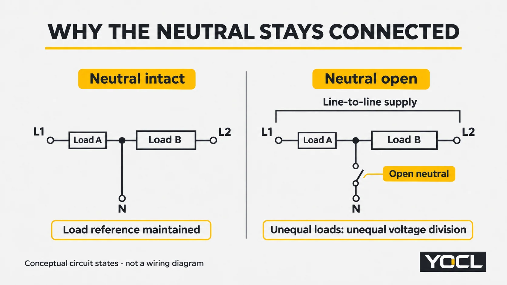
This explains why neutral is not simply another interchangeable cable in the bundle. The sequence preserves it through every phase connection and disconnection. A suspected loose or damaged neutral is a reason to stop and isolate the system for qualified assessment, not to reseat it while the other conductors remain energized.
Phases last
After ground and any required neutral are established, connect the phase conductors according to the equipment’s identified positions and instructions. The protective dependency is between conductor functions: ground before neutral before phases. There is no additional universal safety hierarchy between the individual phases themselves.
That does not mean phase identity is optional. A, B and C, or the corresponding system designations, must remain correctly identified. The temporal order of mating the three phase connectors is different from phase rotation, which describes the electrical sequence of the supply. Following a familiar left-to-right mating order does not prove correct rotation.
Trystar includes a phase-rotation verification procedure for its docking station. The installation’s required rotation must be established before the load is energized, using the approved commissioning method. Any measurement that requires an energized source belongs to that qualified-person procedure; it is not permission to mate or unmate energized connectors. [1]
Mechanical completion matters too. Trystar requires its connections to be fully inserted and turned to the stop. Follow the exact connector’s engagement instructions; do not transfer a turning angle from another series. A connector pushed partly together is not a completed connection merely because it appears to occupy the right position.
Disconnect in exact reverse — and never under load
The removal sequence is phases, neutral, ground. Every phase connection must be removed before the neutral, and ground remains until last. Reversing only the physical direction along a panel is not enough: the order is defined by conductor function.
Before any connector is disturbed, the applicable supply must be isolated and the deenergized condition verified. A stopped generator, an extinguished indicator or an unloaded downstream appliance does not establish that the connector is safe to separate. Relevant sources and possible backfeed must be addressed by the site procedure.
OSHA’s US workplace rule requires a qualified person to verify the deenergized condition with test equipment and addresses unexpected backfeed. Its scope is US occupational work; local rules apply elsewhere. This article’s sequence assumes that isolation and verification have already been completed. [5]
Actsafe warns against making or breaking cam lock connections under load because of arcing hazards. Do not treat a cam lock as a load-break device unless the exact model documentation expressly gives that capability. No such declaration appears on the YOCL pages reviewed here. An emergency is a reason to operate the designated upstream disconnecting means under the emergency procedure, not to pull a connector carrying load. [4]
Identification traps: colours, gender and panel direction
Green for equipment ground, white or gray for neutral, and black/red/blue for phases are familiar North American temporary-distribution cues. They are not a globally interchangeable connector specification. OSHA’s conductor-identification guidance distinguishes grounded and equipment-grounding conductors; the phase examples in the Connecticut Electric-hosted instructions belong to that equipment’s system configurations. [2, 6]
Those instructions also show brown/orange/yellow phase identifiers for a different voltage configuration. Actsafe describes Canadian entertainment conventions with a different phase-colour ordering. Neither example establishes a colour offering for YOCL products or allows a cable’s function to be inferred from its sleeve alone.
Gender can create another false shortcut. Actsafe describes entertainment arrangements with ground and neutral connector genders reversed relative to the phase connectors, as well as arrangements reversing ground alone. These configurations help distinguish functions in those systems, but the convention is not identical across all equipment and rental fleets. [4]
Panel left-to-right arrangement is not a universal sequence. It can differ between equipment and viewing directions. Follow designated functions rather than a familiar visual direction.
Colour and gender are clues only: verify every conductor’s identity against labels and appropriate testing. If labels, cable records and the equipment documentation disagree, resolve that discrepancy before energizing. Do not improvise an adapter or reassign a connector’s function to make the colours appear consistent.
Why some rigs run two neutrals
A second neutral connection can reflect a real load characteristic. Nonlinear loads, including some dimming and electronic equipment, can introduce harmonic currents that increase neutral loading in a three-phase four-wire system. Neutral current can exceed phase current; apparently balanced phase loads do not exclude harmonic loading. The US Department of Energy describes increased neutral loading, and AXA XL explains how additive harmonics can make it exceed phase current. [7]
Some entertainment distribution equipment consequently provides double neutral connections. PRG’s documented distribution equipment is one such example, identifying additional neutral connections for excessive neutral current. That example explains why another neutral position may appear; it does not establish a parallel-conductor specification for another assembly. [8]
Where the documented design requires multiple neutral connections, all required neutrals belong to the neutral stage: establish them before phases and retain them until phases are removed. Never assume an extra neutral socket is spare or that one connected neutral is sufficient. Cable sizing, parallel arrangements and connector loading require the equipment’s approved design. This article supplies no YOCL parallel-neutral rating.
What YOCL’s pages do and do not declare
YOCL’s cam lock connector category contains four single-pole formats:
- Cable plug, with a plug contact, elongated grip body and tapered cable-entry tail.
- Cable connector, with a socket-contact cavity, elongated grip body and tapered cable-entry tail.
- Panel-mounted plug, with a plug contact, four-hole mounting flange, hinged cover and rear threaded connection.
- Panel-mounted socket, with a socket-contact cavity, four-hole mounting flange, hinged cover and rear threaded connection.
The public information establishes these formats and visible structural features. The reviewed pages do not declare current, voltage, accepted conductor size, ingress-protection rating or an available conductor-colour configuration. Cable-entry drawing callouts are not an electrical ampacity table or a conductor-area selection table. A pictured finish does not establish the available colour scheme.
Use the cable-plug product page and panel-mounted socket product page to identify the exact format for document review. These are not a recommendation to use an unspecified model in a temporary-power installation.
Before project use, obtain written confirmation for the exact model of:
- Rated current under the intended conditions.
- Rated voltage for the intended supply.
- Accepted cable and conductor range, including the relevant termination instructions.
- Male/female contact arrangement and the documented mating counterpart.
- Available colour configuration and the method used to identify each conductor function.
Ask for the applicable model documents and any project-required approval evidence. No published YOCL page reviewed here establishes cross-brand interchangeability, NEC compliance, UL listing or load-break capability. A generic cam lock description cannot fill those documentary gaps. The sequence rule explains conductor dependencies; it does not approve an accessory or a complete installation.
Pre-energizing checklist
Use this as a review record within the equipment-specific work procedure, not a substitute commissioning instruction. An unresolved item means the system is not ready for release.
| Review item | What must be established |
|---|---|
| Equipment grounding | Correct conductor identified and protective connection established |
| Neutral, where required | Every neutral connection required by the design is present and complete |
| Phase identity and rotation | Labels correspond to the intended circuit; required rotation has been verified by the approved method |
| Full engagement | Every connector is completely inserted and locked according to its own instructions |
| Electrical suitability | Exact-model ratings, cable acceptance and mating configuration are documented for the project |
| Isolation during mating | Connection work was completed deenergized; no connector is being used as the load-breaking means |
| Release for energization | Required checks are complete and personnel are clear under the site procedure |
Record findings against the actual equipment identifiers. Correct order leaves identity, engagement and suitability unresolved; these checks answer different safety questions.
FAQ
Does the order really matter if the power is off while I connect?
Yes. Isolation is essential, but the completed connection must also have the required protective and neutral paths when supply becomes available. Ground first, neutral next where used, phases last preserves those dependencies. Equipment interlocks and the inspected manuals use a defined sequence; an assumption that power will remain off does not justify abandoning it.
What happens if the neutral comes off before the phases?
If the circuit becomes or remains energized, unequal line-to-neutral loads can be left sharing a line-to-line supply. Their voltage division becomes load-dependent, and equipment can experience overvoltage approaching the system’s line-to-line voltage. It is not the same fixed voltage in every system. Isolate for qualified assessment; do not reconnect a suspected open neutral live.
Can I connect or disconnect cam locks under load in an emergency?
No. Use the designated upstream disconnecting means under the site emergency procedure, then isolate and verify before disturbing connectors. Do not assume load-break capability unless the exact connector’s documentation expressly establishes it. The YOCL pages reviewed for this article do not make that declaration. Urgency does not make an ordinary separable connector a switch.
Are cam lock colours the same everywhere?
No. North American ground, neutral and phase colour conventions have system and regional variations, and entertainment equipment can use different ground/neutral gender arrangements. Colour, gender and left-to-right panel position cannot establish conductor identity on their own. Confirm each function from labels, the equipment documentation and appropriate testing before energization.
What if the set has no neutral?
Where the documented supply and load arrangement does not use a neutral, omit that stage: connect equipment ground before phases, and disconnect phases before ground. The cited NEC commentary expressly qualifies the grounded-conductor stage with “where used”. A missing neutral cable is not evidence that a neutral is unnecessary; confirm the required circuit arrangement first.
Sources
- Trystar, Horizontal Generator Docking Station Installation, Operation and Maintenance Manual, pp. 5-6 and 9. Equipment-specific connection, engagement and phase-rotation instructions; no ratings transferred to YOCL.
- Power Assemblies, Quick Connect Switch Operating and Maintenance Instructions, hosted by Connecticut Electric, p. 1. Connection order and equipment-specific colour variants.
- Mark C. Ode, Powering Up: Temporary Generators, Electrical Contractor, May 15, 2009. Historical NEC commentary, not the current adopted code text.
- Actsafe Safety Association, Live Performance Electrical Certificate Candidate Study Guide, revised July 2012, pp. 20-22. Educational explanation of connection order, load hazards and identification variants.
- OSHA, 1910.333: Selection and use of work practices, particularly verification of deenergized condition. US workplace scope.
- OSHA, Electrical training material, conductor-identification section. Educational background, not a universal connector-colour specification.
- US Department of Energy, Electricity Distribution System Baseline Report, section A.3.2.1, printed p. A.14; AXA XL Risk Consulting, Electric Power Quality and Reliability, 2020, p. 6. Neutral-harmonic mechanisms only; no numerical thresholds reproduced.
- PRG, Lighting Systems Networking Guide, printed p. 9. Documented double-neutral equipment example; no numerical ratings reproduced.
- YOCL ELECTRIC, cam lock category and product information linked in the YOCL section above; all four format pages reviewed November 10, 2026. First-party structural declarations and public specification limits.