
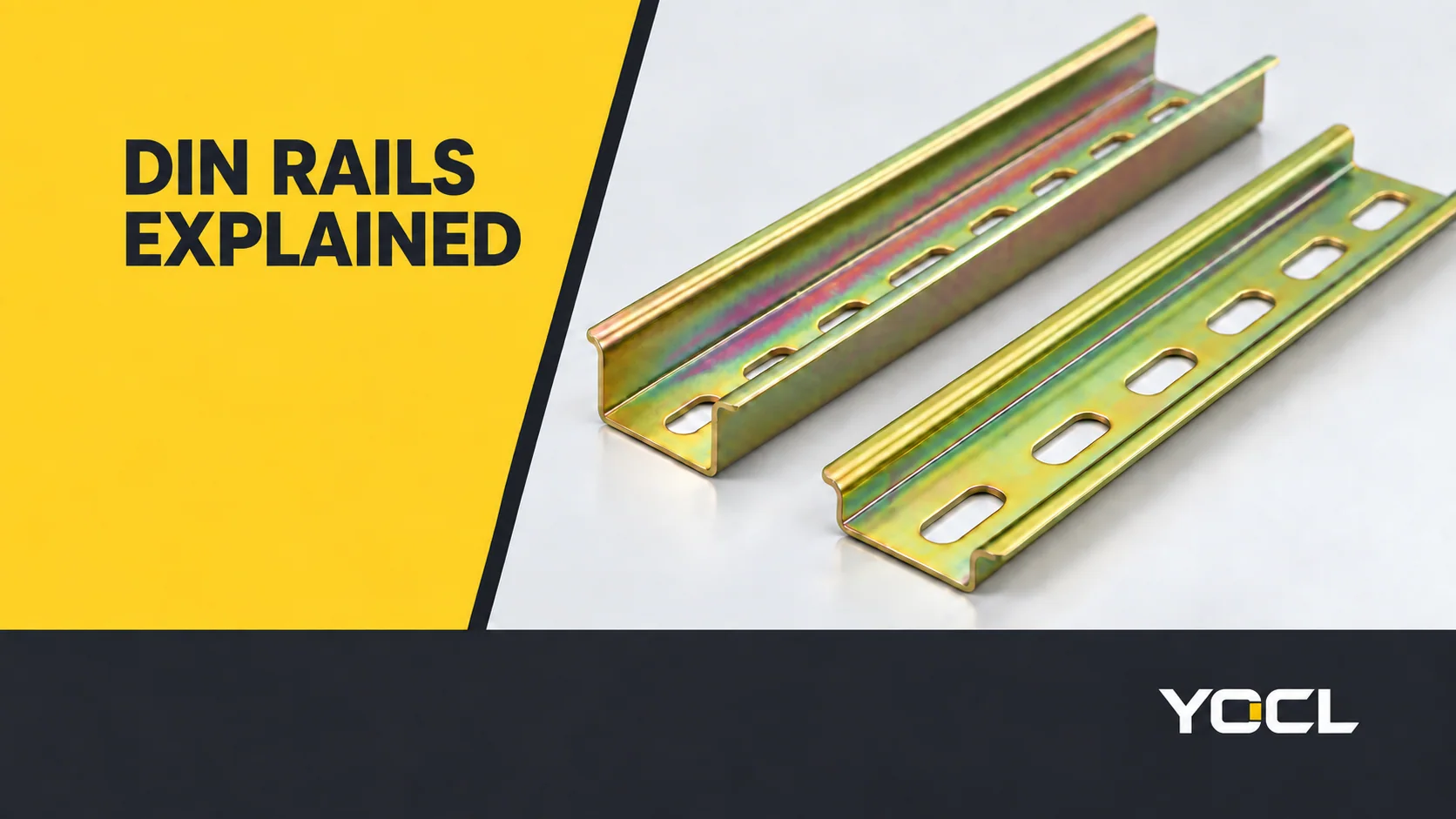
A DIN rail is a formed mounting profile that supports compatible electrical devices inside a panel or enclosure. Its section engages the device’s mounting foot; its fixing arrangement attaches the rail to the panel. Profile, depth and accessory fit must be checked together: a DIN label or nominal width alone does not establish compatibility.
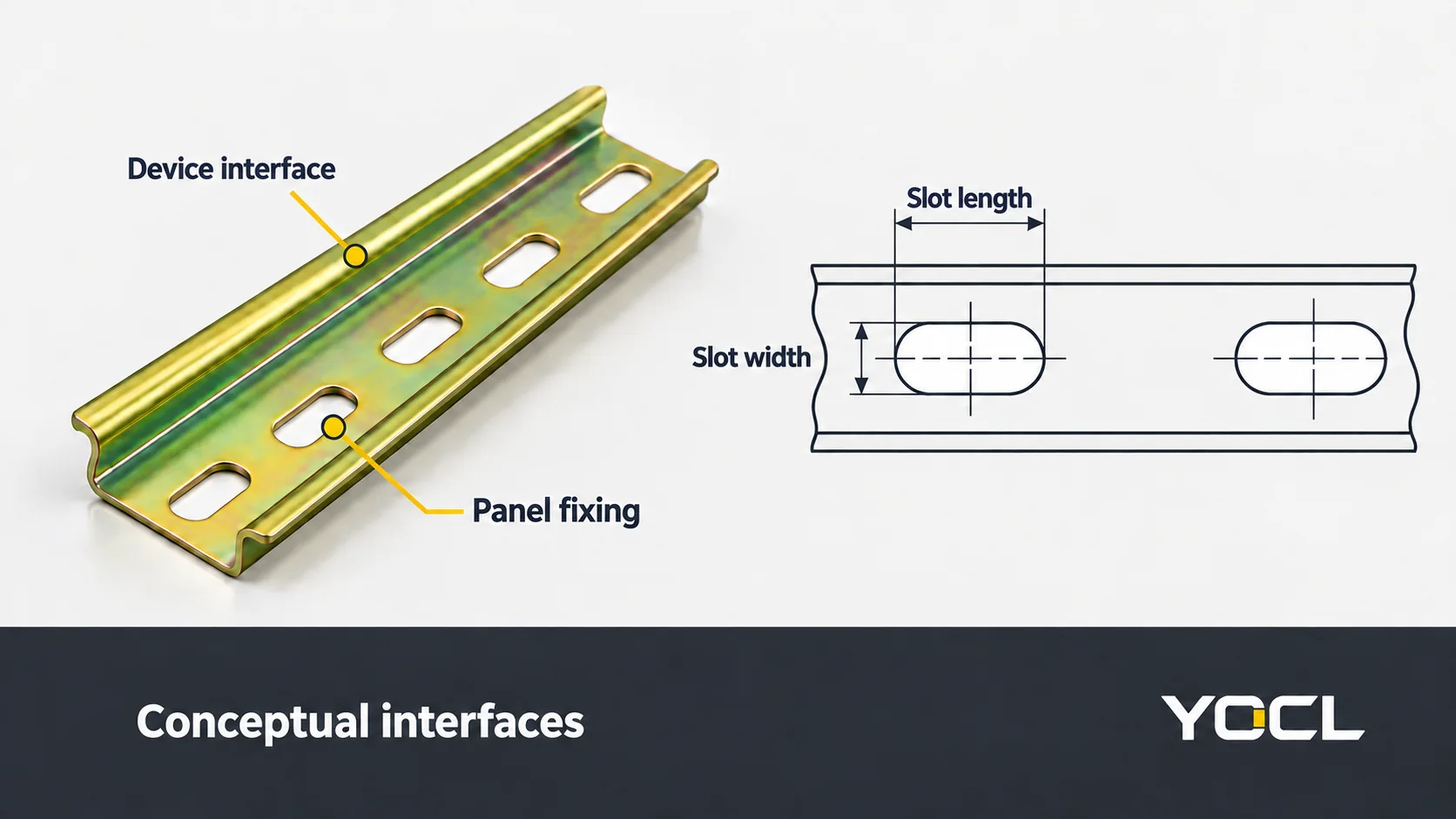
A rail has two mounting interfaces
Read the assembly in this order: device mounting foot → rail section → rail fixings → panel or backplate.
The first interface determines whether the device engages the rail. The second determines how the rail attaches to its supporting structure. A terminal that clips onto the section does not, by itself, establish the suitability of the panel fixings or the completed assembly.
IEC 60715:2017 addresses dimensional and functional requirements for compatible mechanical rail mounting. Its public preview separates mounting compatibility from functional interchangeability. Sharing a mounting interface does not make devices electrically equivalent.
Recognize the section before comparing dimensions
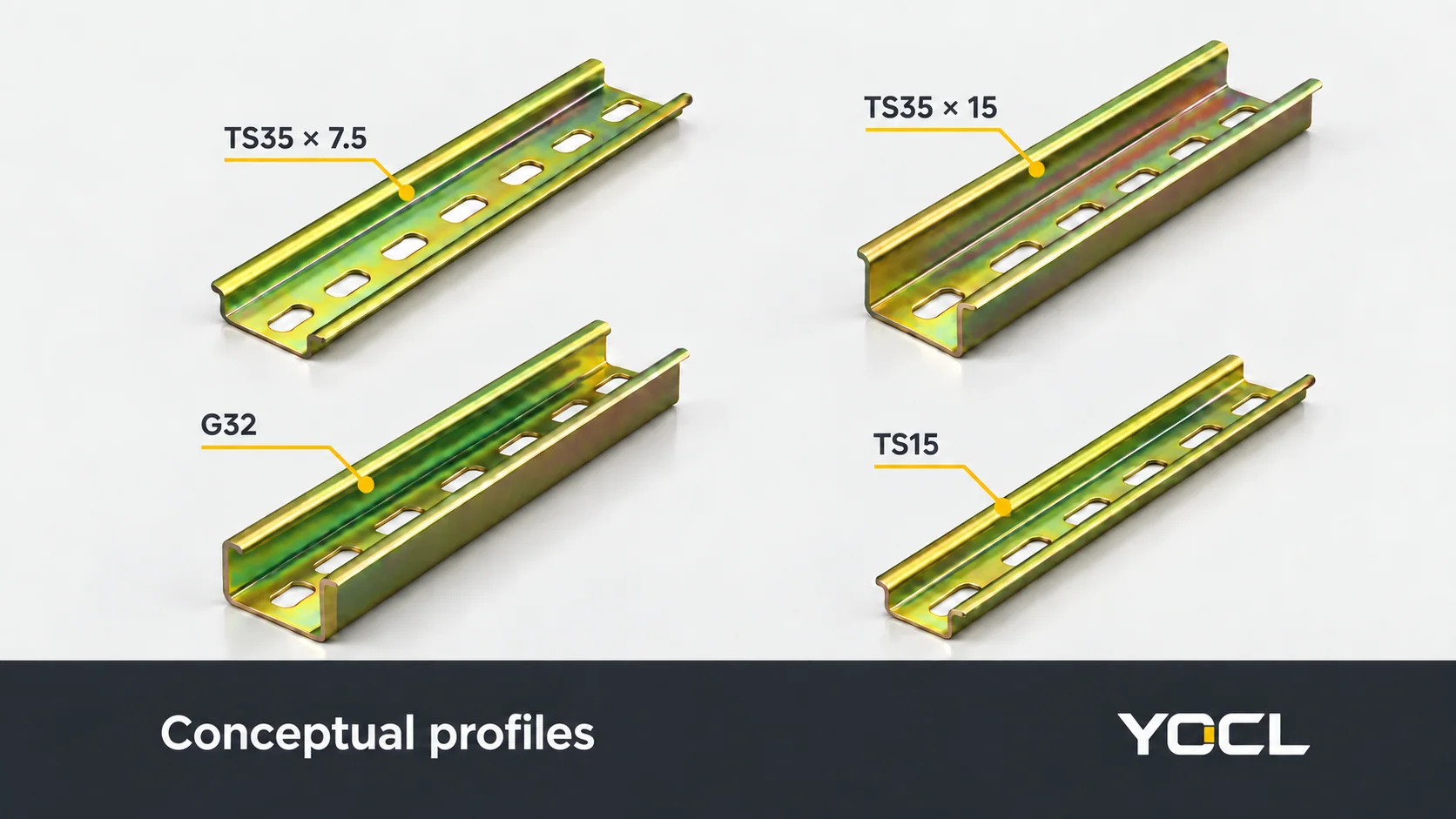
YOCL’s principal rail profiles can be distinguished by width, section depth and flange shape:
| Profile in the YOCL range | Recognizable section | First fit question |
|---|---|---|
| TS35, 35 × 7.5 mm steel | Symmetric top-hat section, 35 mm wide and 7.5 mm deep | Does the device specify this section and depth? |
| TS35, 35 × 15 mm steel | 35 mm top-hat section with greater depth | Does the mounting foot accept it, with sufficient installed clearance? |
| G32 steel | Asymmetric 32 mm G-profile | Does the device accept the G-section flange arrangement? |
| TS15, 15 × 5.5 mm mini steel | Narrow top-hat section | Is the device specified for the smaller TS15 interface? |
These are YOCL product descriptions, not a complete table of standard tolerances. The G32 record identifies unequal 15/9 mm flange projections; it is not a slightly narrower substitute for a symmetric TS35 rail. TS15 also needs its own compatible mounting foot.
The IEC preview identifies C-section rails as another family. They need their corresponding mounting arrangement; a top-hat rail clip should not be assumed to fit them.
The two TS35 heights need a documented device match
The second number in 35 × 7.5 or 35 × 15 describes section depth. It does not describe sheet thickness or slot size.
For a device accepting both sections, changing rail depth changes the panel layout to review: installed device position, wiring access, nearby obstructions and space for its release mechanism. A deeper rail is not automatically a compatible replacement merely because its nominal width is unchanged.
There are products with an explicit two-height declaration. YOCL SJ cage-spring terminal blocks list TH35-7.5 or TH35-15 in their mounting table. That is positive evidence for the stated SJ range; it is not evidence that every DIN-mounted product accepts both.
You will therefore encounter TS35 in rail descriptions and TH35 in mounting specifications. Match the actual section and dimensions stated by the device, rather than treating the prefix as the whole compatibility check.
Keep section, thickness and fixing openings separate
A purchase description such as “35 mm slotted rail” leaves several fields unresolved:
| Field | What it describes | What it does not establish |
|---|---|---|
| Profile width and depth | The cross-section presented to the mounting foot | Material thickness or device approval |
| Nominal material thickness | The specified steel or aluminium section thickness | Overall profile depth or a universal load rating |
| Slot width × length | The size of an individual fixing opening | Slot pitch, screw size or complete fixing layout |
| Fixing pitch or hole layout | The positions of successive fixing openings | The opening dimensions alone |
| Overall rail length | The supplied rail run | The space remaining after devices and accessories are fitted |
For example, YOCL’s 35 × 7.5 mm steel standard-slot configuration lists 0.9, 1.0 or 1.2 mm nominal thickness with 6.2 × 15 mm slots. Its long-slot configuration lists those thickness choices with 5.2 × 25 mm slots. Keep the configuration row together; neither slot dimension supplies the fixing pitch.
The published 35 × 15 mm steel rail instead specifies 1.5 mm nominal thickness and 6.2 × 15 mm slots. Here, 15 mm section depth and 15 mm slot length happen to share a number while describing different geometry.
Slotted and unslotted describe the presence of fixing openings, rather than a different device-mounting family. The required fixing layout still belongs to the selected rail and panel arrangement.
Mounting means device retention and panel fixing
The IEC preview describes direct clip-on mounting and mounting through specified accessories as distinct approaches. Follow the device’s documented method; the rail label does not supply an insertion angle, release procedure or adapter design.
On the panel side, match the rail’s openings to the specified fastener and receiving arrangement. Check head clearance, attachment to the backplate and the fixing positions against the relevant drawings. An opening that admits a screw does not establish the correct screw, its tightening instruction or the suitability of the receiving structure.
Support layout also matters. Obtain the rail/device guidance for the intended loading and fixing arrangement rather than assigning one screw interval or working load to every TS35 rail. Include material, thickness, unsupported spans and mounted equipment in that review.
Reserve space for the device’s documented installation and removal access, not just its resting outline. The release tool or motion can require space beyond the device body.
Accessory fit belongs to the interface it serves
A rail-mounted restraint and a terminal-side accessory are matched to different geometry:
| Accessory | Interface to match | Information to obtain |
|---|---|---|
| End stop or end clamp | Its rail engagement and row-retaining arrangement | Accepted rail section and specified fixing instructions |
| Mounting adapter or support | Device attachment and the intended rail/panel interface | Approved mating geometry and assembly arrangement |
| Terminal end plate or partition | The terminal housing and series | Exact model/series accessory reference |
| Bridge or jumper | Terminal connection positions and pitch | Documented terminal models and connection configuration |
| Marker | The terminal’s marking location | Compatible marking part and label arrangement |
An end plate closes an applicable terminal housing side; an end stop restrains the row. One does not substitute for the other. A common mounting rail also does not establish compatibility between the jumpers or covers of different terminal series.
YOCL’s UK terminal record illustrates the distinction: jumpers and end plates are model-specific, while enclosed-housing models including UK-35N require no separate end plate. Avoid adding a plate to every terminal merely because it sits on a DIN rail.
For conductor connections and terminal circuit functions, use What Is a Terminal Block? Connection Types and DIN Rail Accessories. Those decisions remain separate from selecting the rail section.
Material and electrical duty need their own evidence
YOCL’s DIN rail range includes steel and aluminium configurations with different thicknesses, slots and lengths. Specify the actual material and finish required by the project. A metallic colour or “blue-white” appearance does not establish a coating specification or corrosion class.
A mechanical rail is also not a substitute for a supply busbar. For protective-earthing duty, IEC 60715’s scope points to the relevant product requirements, including IEC 60947-7-2 for a rail’s conducting connection to protective-conductor terminals. Rail appearance or an ordinary mounting clip does not establish that protective connection.
Choose the next document by the unresolved fit
| Remaining question | Next resource |
|---|---|
| Which profile forms are available? | YOCL DIN rail range and the profile records above |
| Will this device accept the selected rail height? | Its exact mounting specification; SJ is one documented two-height example |
| Will the rail attach to this backplate? | Rail configuration row, fixing-layout drawing and specified mounting instructions |
| Which restraint, plate or bridge fits? | The rail accessory’s engagement data or the terminal’s model-specific accessory schedule |
For a fit review, send the device mounting reference, rail section, material, nominal thickness, slot dimensions and required fixing layout, rail lengths, accessory models, service conditions and quantities. A panel drawing connects those separate requirements into one assembly for review.
References
- IEC — IEC 60715:2017, edition 2.0; public catalogue and official preview Introduction and Scope only for mechanical mounting and protective-earthing boundaries; no full-standard review.
- YOCL ELECTRIC — 35 × 7.5 mm Slotted Steel DIN Rail; first-party section and configuration data.
- YOCL ELECTRIC — 35 × 15 mm Slotted Steel DIN Rail; first-party depth, thickness and opening dimensions.
- YOCL ELECTRIC — 32 mm Steel G-Profile DIN Rail; first-party asymmetric section information.
- YOCL ELECTRIC — 15 × 5.5 mm Mini Steel DIN Rail; first-party TS15 profile information.
- YOCL ELECTRIC — SJ Cage Spring DIN Rail Terminal Blocks; first-party TH35-7.5 / TH35-15 mounting declaration.
- YOCL ELECTRIC — UK Series Screw DIN Rail Terminal Blocks; first-party model-specific accessory and enclosed-housing information.
- YOCL ELECTRIC — DIN Rails Manufacturer; first-party material/configuration range and finish-selection boundaries.