
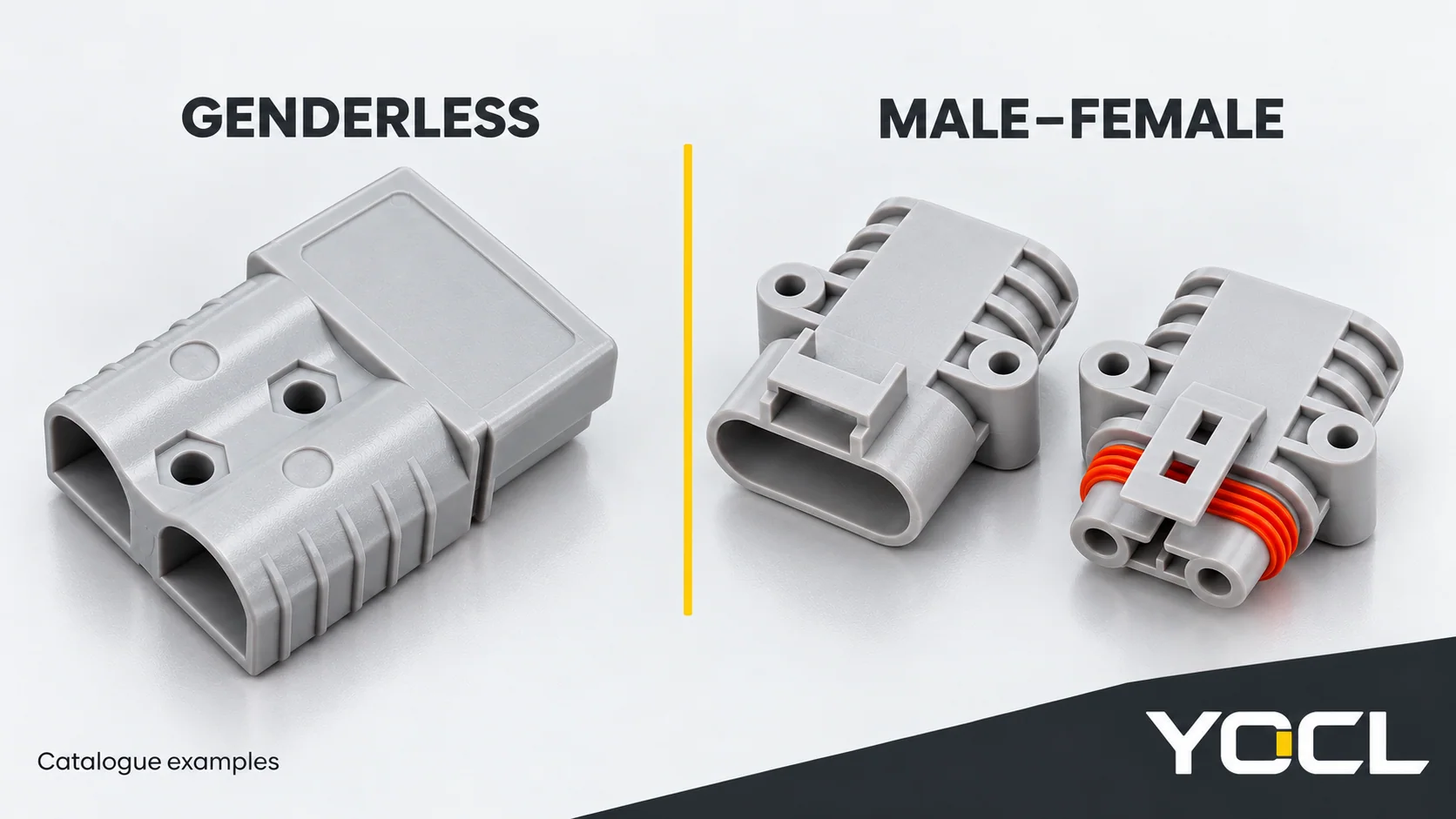
Choose a documented genderless pair when the equipment design can use the same mating-interface type on both sides. Choose a documented male–female pair when the equipment requires complementary halves or an existing interface specifies them. Either format can be appropriate; acceptance still requires the exact counterpart, contact arrangement and circuit assignment. If those are unresolved, neither is ready to approve.
Genderless describes the mating format. Male and female describe complementary contact or connector forms. None of these terms assigns battery positive, battery return, charger side or load side by itself. Mechanical fit and correct polarity need separate evidence.
This comparison addresses that decision and its checks. The battery connector overview covers the wider product landscape, contact construction and rating questions.
Compare the formats for the same equipment requirement
Hold the electrical duty, cable requirements, environment and service operation constant. Changing those conditions while comparing connector names can conceal the actual reason one candidate is unsuitable.
| Requirement or condition | Genderless format | Male–female format | Decision rule |
|---|---|---|---|
| Existing equipment specifies an exact mating interface | Use only its documented counterpart, including contact and housing variants | Use the specified complementary half and contacts | The existing interface governs; changing format is a design change |
| A new interface is intended to use a common connector type at both ends | A candidate if the approved parts schedule confirms that common type and its matching orientation | Separate complementary parts must be identified and managed | Consider genderless for the common-interface requirement; verify actual part references before claiming stock simplification |
| Distinct mating halves are part of the equipment’s assembly plan | Do not substitute a same-type interface without reviewing that plan | Can provide the required distinction when the specified pair is documented | Use the defined assembly architecture; sex does not independently assign source and load |
| Several nearby circuits must not be cross-connected | Needs an established matching/keying scheme for those circuits | Also needs an established matching/keying scheme | Choose the documented scheme that prevents the relevant unintended pairings; either or neither may satisfy it |
| The disconnected source-side connection needs specified contact protection | The format name does not establish protection | The format name also does not establish protection | Obtain evidence for the exact exposed state, equipment and mating half |
| Mating references, circuit assignment or duty evidence are missing | Not established | Not established | Resolve the missing information before approving either |
Two YOCL catalogue entries illustrate the formats: the 120 A double-pole power connector is described as genderless; the 50 A parking-air-conditioner connector uses separate male and female housings and contact forms. These are different product families, not equal-duty alternatives or interchangeable halves. Their current labels identify the examples; they do not decide the comparison above.
Check one: establish the mechanical pair
Identify housings and contacts independently
Record the manufacturer, complete housing reference, contact reference and any keying or colour variant for both ends. “Two-pole battery connector” or “the grey one” leaves too much unresolved.
For a genderless design, confirm the designated same-type mating arrangement. Do not extend that designation to another series, housing colour, contact variant or supplier. Genderless does not mean that any two similar housings are an approved pair.
For a male–female design, identify the complete complementary parts. A housing description and a contact description can refer to different features; an outer shell’s appearance is insufficient to classify its contact interface. Record which pin/contact and socket/contact references belong in each specified housing rather than inferring them from a sales photograph.
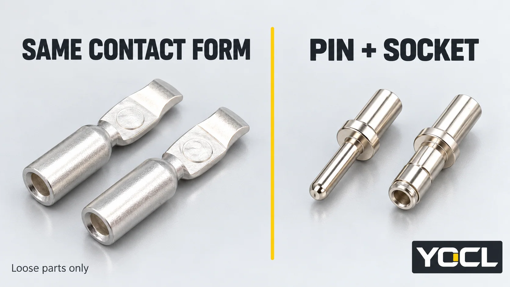
The two example pages establish the stated formats, but their public descriptions do not supply a complete equipment pin assignment. Request the matching schedule and equipment drawing for the proposed connection. If that evidence is missing, record the pair as unconfirmed rather than treating a visual match as approval.
Separate keying, retention and circuit identity
Keying concerns permitted mechanical pairing and orientation. Retention concerns how the connection stays together. Circuit identity concerns what each contact connects to. A latch engaging cannot establish all three.
Check the permitted variants against the actual mating drawing. If colour participates in a particular family’s matching scheme, retain that specification in the parts record. Do not apply a universal red/grey/blue compatibility or voltage rule to the whole battery-connector catalogue.
For repeated or nearby interfaces, record intended pairs and prohibited pairs. If the design depends on preventing an unintended connection, obtain the corresponding mechanical evidence. A label can help identify a connection, but it does not physically prevent a compatible wrong counterpart from engaging.
Check two: establish the electrical correspondence
Use a stated view and reference feature
Before comparing contact positions, read how each drawing defines its view: looking into the mating face, looking from the wire-entry end, or another explicitly identified view. Also identify its orientation reference, such as the documented key or latch position.
The same physical position can appear on different sides when viewed from opposite ends. Copying “left wire” from a rear-view sketch into a mating-face sketch can therefore create a false correspondence. Do not assume a particular mirroring or rotation rule for every housing. Use the manufacturer’s position identifiers and the drawing’s stated orientation to relate the views.
A product photograph may show wire-entry openings rather than the mating face. Without a documented reference, it cannot serve as a pinout. Do not add cavity numbers or positive/negative marks to that photograph and then treat them as model data.
Map circuit functions without assigning them from connector sex
Use the equipment’s circuit drawing to identify each conductor’s function at each end. Record the contact position using its real documented identifier. Keep conductor colour as an identification aid within that drawing’s convention; it is not independent proof of the connected net.
The following is a hypothetical record for a direct two-conductor direct-current (DC) supply connection. It illustrates logical correspondence, not a YOCL cavity layout or an instruction for a particular battery system.
| Circuit function in this assumed design | Required correspondence across the interface | Evidence needed |
|---|---|---|
| Battery positive supply net | Equipment’s designated positive input net | Approved circuit drawing and the actual position-to-net assignment for both halves |
| Battery return net | Equipment’s designated return input net | The corresponding return-path assignment in those same drawings |
| Any additional position, if present | Its separately defined circuit function | A specific assignment; do not infer function from size, location or housing sex |
Neither “positive on the left” nor “male goes to battery” is a general result of this example. Follow the equipment drawing, including any separately defined circuits. A pair that accepts the correct mechanical orientation can still contain an incorrect conductor assignment.
Keep verification within the equipment’s safe procedure
Do not connect a battery to find out whether an assumed assignment works. Equipment switched off may still leave a battery-connected interface energized. Have competent personnel establish the appropriate safe state before inspection or electrical verification. The UK Health and Safety Executive’s HSG85 guidance, pages 20–22, addresses identifying equipment, disconnecting sources, secure isolation and proving dead; it is UK guidance, not a connector-specific battery procedure.
Continuity verification belongs to a suitably isolated harness under an approved method. Do not apply an assumed continuity check to a battery-connected circuit. Any necessary energized measurement requires its own competent, equipment-specific procedure; no live probe points or test settings are prescribed here.
A successful harness-mapping check also does not establish permission to connect or disconnect under load. The IEC 61984:2008 public preview, definitions 3.8–3.9 and 3.27–3.28, distinguishes carrying current from the specified making/breaking function. Its interlock definition, 3.12, is separate from an ordinary retention latch. These definitions explain the evidence boundary; they do not certify either YOCL example or authorize its operation. See the original public preview.
Record an outcome for each check
Keep the mechanical and electrical findings separate in the pair record. This prevents a successful check from being used to excuse an unresolved one.
| Available evidence | Outcome to record | Next action |
|---|---|---|
| Exact counterpart confirmed; circuit assignment unresolved | Mechanical pairing established, electrical correspondence pending | Obtain the equipment position-to-net schedule and approved verification |
| Circuit mapping appears consistent; counterpart references unconfirmed | Circuit mapping recorded, mechanical pairing pending | Confirm housing/contact variants and mating evidence |
| Both checks established; intended duty or operating permission unresolved | Pair/mapping checks complete, application acceptance pending | Resolve the electrical, environmental and service-operation requirements |
| Any drawing, part identity or check conflicts | Hold for review | Resolve the conflict; do not force mating, alter keying or improvise an adapter |
| Pair, mapping, duty and operation are documented and verified through the applicable procedure | Ready for the responsible person’s application acceptance | Retain the approved record and configuration |
For a new interface, either format remains a candidate until that record is complete. For a replacement, preserve the existing approved interface unless an authorized design change establishes the alternative. Cross-brand substitution and adapters require their own compatibility and circuit evidence; matching shape and amperes are insufficient.
A useful record includes both housing/contact references, drawing revisions, view orientation, intended and prohibited pairs, actual circuit assignments, verification results and the responsible approval. Keep unresolved fields visible instead of filling them from a photograph or a familiar colour scheme.
For a review through the YOCL battery and power connector range, send both counterpart references or drawings with that record and the intended duty. Specify whether you are confirming an existing mate, choosing a new format or reviewing a proposed substitution so the required evidence is clear.
References
- YOCL product information, 120 A Double-Pole Power Connector—declared genderless format and original exterior/contact imagery; reviewed November 2, 2026.
- YOCL product information, 50 A Waterproof Parking-Air-Conditioner Connector—declared male/female construction and original housing/contact imagery; reviewed November 2, 2026.
- UK Health and Safety Executive, Electricity at work: Safe working practices (HSG85), third edition, 2013, pp. 20–22—UK guidance on safe dead working.
- IEC, IEC 61984:2008 original public preview, definitions 3.8–3.9, 3.12 and 3.27–3.28—operation and interlock distinctions only; full paid standard not consulted.