
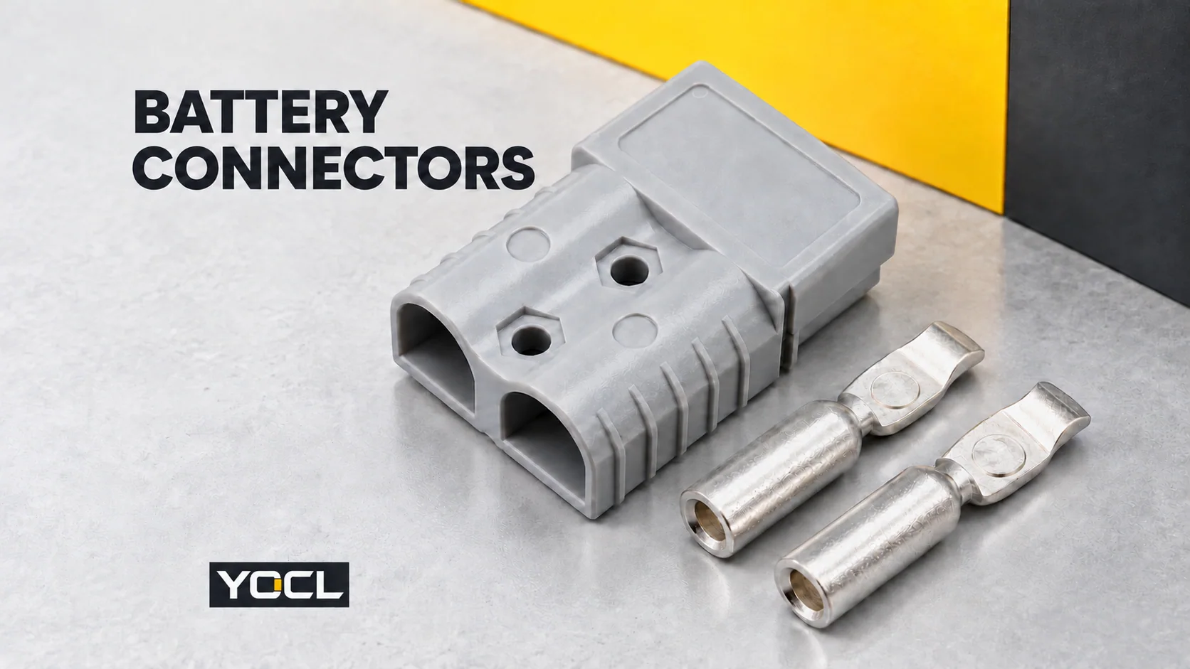
A battery connector is a separable electrical interface connecting a battery circuit to a charger, load or another assembly. Its metal contacts carry current and terminate conductors; its insulating housing locates the contacts and shapes the mating interface. A complete connection requires matched mating parts and a defined circuit assignment.
This guide focuses on industrial cable-side battery and power connectors. Cell-holder contacts and small circuit-board battery interfaces are other forms of battery connection, with different construction and selection questions.
The connector’s defining feature is its mating interface: the connection can separate there while the conductors remain terminated. This follows the connector concept in the IEC 61984:2008 public preview, §3.1. A cable splice instead joins conductors at their termination; the wire-connector guide covers those joining arrangements.
A Power Contact Has Two Different Ends
Look at the loose metal contact before reading the housing’s current label.
| Part or feature | Job in the connection | Information needed |
|---|---|---|
| Cable termination or barrel | Connects the conductor to the metal contact | Accepted conductor, terminal variant and preparation/tooling instructions |
| Mating end of the contact | Engages the corresponding contact across the separable interface | Matching contact geometry and counterpart |
| Insulating housing | Positions the contacts and defines the physical interface | Housing model, contact retention, keying and orientation |
| Retention or sealing parts, where supplied | Address particular mechanical or environmental features | Required parts and the completed configuration |
YOCL’s 120 A double-pole power connector provides a useful exterior example: two contact positions in a polycarbonate (PC) housing, with silver-plated copper contacts. Its pictured loose contacts have a tubular cable end and a shaped mating end. They are two features of one component, not interchangeable dimensions.
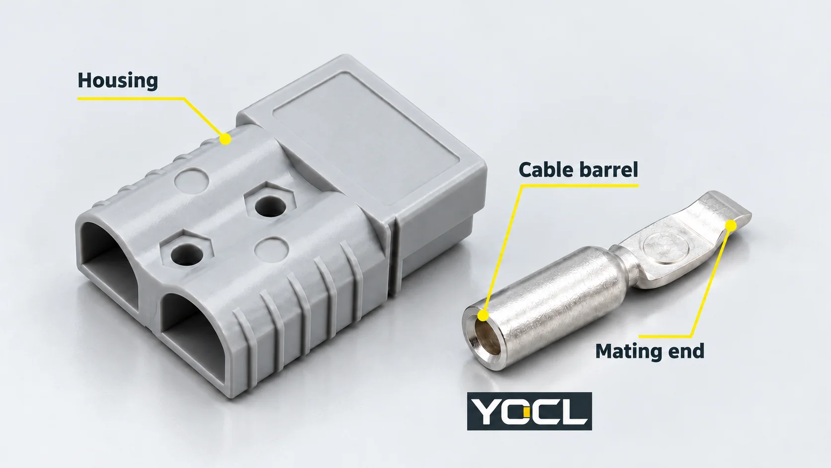
The housing, contact and cable must be specified together. An empty housing is not a terminated connector, and a contact that accepts the cable is not automatically the correct contact for that housing.
For a rectangular assembly built from inserts, hoods and mating shells, use the separate heavy-duty connector guide. That component schedule differs from the cable-contact-and-housing formats here.
Pole Count and Mating Format Answer Different Questions
A single-pole housing provides one main contact position. Double- and three-pole bodies group more main positions in one housing. Pole count describes the connection arrangement; it does not assign positive, negative or another circuit function.
The YOCL battery and power range separates single-, double- and three-pole power forms from male/female forklift and vehicle forms.
Genderless Connections
In a documented genderless design, mating does not require separately designated male and female connector types. The selected housing and contacts still need their specified counterpart and orientation.
YOCL lists the 120 A double-pole form as genderless. That statement is about its mating design. It does not establish that every similarly shaped connector, every housing colour or another manufacturer’s part will mate correctly.
Pin-and-Socket Connections
Other designs use distinct pin and socket contacts with corresponding housing halves. YOCL’s 50 A parking-air-conditioner connector shows separate male/female housings, metal contact parts, a latch and rubber sealing sleeves.
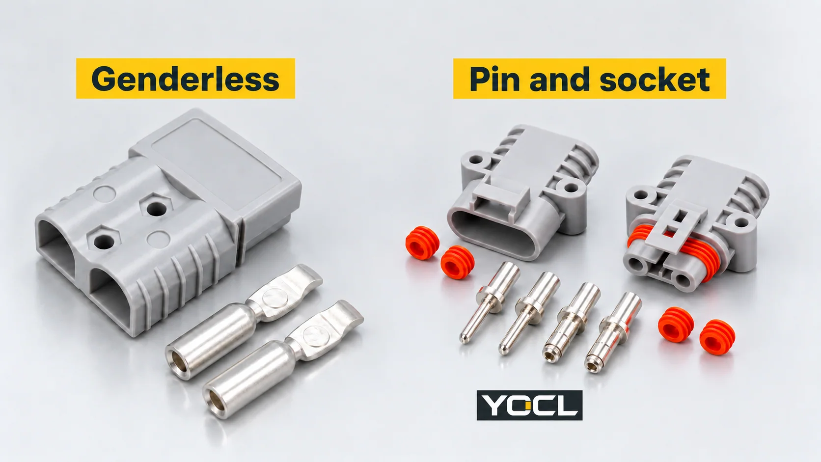
Male or female identifies the contact interface, not automatically the battery side or charger side. Specify both halves and the circuit assignment.
Keying Is Different from Polarity
Keying controls which physical counterparts can engage and in what orientation. Polarity identifies the electrical function assigned to the contacts.
A correctly oriented housing can still have the wrong conductor assignment. Housing colour also needs its exact model context: it may be an ordering or matching detail, but no universal colour-to-voltage or colour-to-polarity rule applies across this catalogue.
Confirm the mating drawing and the equipment’s contact assignment together. A photograph alone cannot establish either electrical compatibility or a cross-brand replacement.
Auxiliary Contacts Need Their Own Circuit Information
Some battery connectors have smaller additional contacts alongside the main power positions.
YOCL’s 75 A double-pole model with auxiliary contacts distinguishes two main power poles from the auxiliary contacts. Its published record does not provide the auxiliary circuit assignments, separate current ratings or engagement sequence.
Record those details separately. The main 75 A figure must not be copied to the auxiliary circuit. Nor does the presence of auxiliary contacts prove a working interlock, communication protocol or first-make/last-break function.
Read the Contact Option and Complete Model
The 120 A double-pole record lists a 10–25 mm² conductor range and explicitly ties it to terminal selection. It describes available contact options, not one barrel that accepts every size equally.
For example, 16 mm² is inside that published interval. It still needs the corresponding contact reference, accepted conductor construction and specified preparation/tooling. The interval alone supplies none of those details.
Even an identical current figure can identify different products:
| YOCL catalogue entry | Declared current | Declared voltage | Housing |
|---|---|---|---|
| 160 A PA-housing forklift connector | 160 A | 150 V | Polyamide (PA) |
| 160 A PC-housing forklift connector | 160 A | 600 V | Polycarbonate (PC) |
These are the manufacturer’s separate declarations. The shared 160 A figure does not prove equal voltage duty, identical contacts or mating compatibility. The first record also declares a 50 mm² contact barrel; that value must not be transferred to the second.
Current capability depends on specified conductor and thermal conditions. IEC 60512-5-2:2002 addresses current-temperature derating tests at elevated ambient temperature. Its public abstract supplies no derating curve for these YOCL products.
Carrying Current Does Not Establish Switching Permission
A connector’s current rating does not, by itself, authorize plugging or unplugging it while energized or carrying load current.
IEC 61984’s visible definitions distinguish current carrying, breaking capacity and permitted live/loaded engagement or disengagement (§§3.8–3.9, 3.27–3.28). Its interlock definition addresses energization or separation, so a fastening latch alone does not establish that function (§3.12).
Obtain the selected connector’s operating instructions and the equipment’s disconnecting arrangement. Neither the photographs nor the catalogue current figure resolves those permissions.
The official IEC 61984 catalogue also has a defined voltage/current scope, including a 125 A-per-contact limit. It is not a blanket qualification for every battery connector or the higher-current entries above. No YOCL compliance is inferred here.
Housing Material and Seal Features Have Separate Limits
The 120 A record declares a PC housing with UL 94 V-0 material flammability. UL Solutions’ plastics flame-test explanation describes classifications assigned to materials under controlled tests. A material classification is not certification of the complete connector.
Similarly, the vehicle connector’s rubber sleeves identify sealing components, but its public data supplies no numerical ingress-protection (IP) rating. Confirm the required mating state, cable fit and supporting environmental evidence rather than assigning an IP value from appearance.
Find the Document for the Unresolved Interface
| Question | Next document |
|---|---|
| What format and main pole count do I need? | Equipment connection drawing and complete connector reference |
| Will these two halves mate? | Exact housing/contact pairing and mating drawing |
| Does the cable fit the contact? | Terminal-option schedule, conductor acceptance and preparation/tooling instructions |
| Which contact carries which circuit? | Equipment pin assignment, including auxiliaries |
| Will the connection carry the specified duty? | Model ratings, conductor/loading conditions and thermal data |
| May it be connected or disconnected energized? | Explicit connector instructions and equipment disconnecting/interlock arrangement |
For an enquiry through the YOCL battery and power connector range, send both mating references or drawings, main and auxiliary circuit requirements, cable details, electrical duty, environment and quantities. A complete pair-and-contact schedule is more useful than a request based only on colour or amperes.
Related reading: genderless and male–female mating arrangements.
References
- IEC — IEC 61984:2008, edition 2.0, original public preview and official publication record — visible connector/operation definitions and catalogue scope; includes the October 2011 corrigendum. Full paid standard not consulted.
- YOCL product information — 120 A Double-Pole Power Connector — housing, contacts, genderless format and terminal-option interval.
- YOCL product information — Battery & Power Connectors — catalogue mating and pole-format map.
- YOCL product information — 50 A Parking-Air-Conditioner Connector — male/female exterior parts, latch and sealing sleeves; no numerical IP declared.
- YOCL product information — 75 A Double-Pole Power Connector with Auxiliary Contacts — main and auxiliary contact distinction.
- YOCL product information — 160 A PA-Housing Forklift Connector — 150 V, PA housing and declared barrel size.
- YOCL product information — 160 A PC-Housing Forklift Connector — separate 600 V, PC-housing entry.
- IEC — IEC 60512-5-2:2002, edition 1.0 — official public abstract on current-temperature derating; full standard not consulted.
- UL Solutions — Combustion (Fire) Tests for Plastics — material flame-classification explanation.