
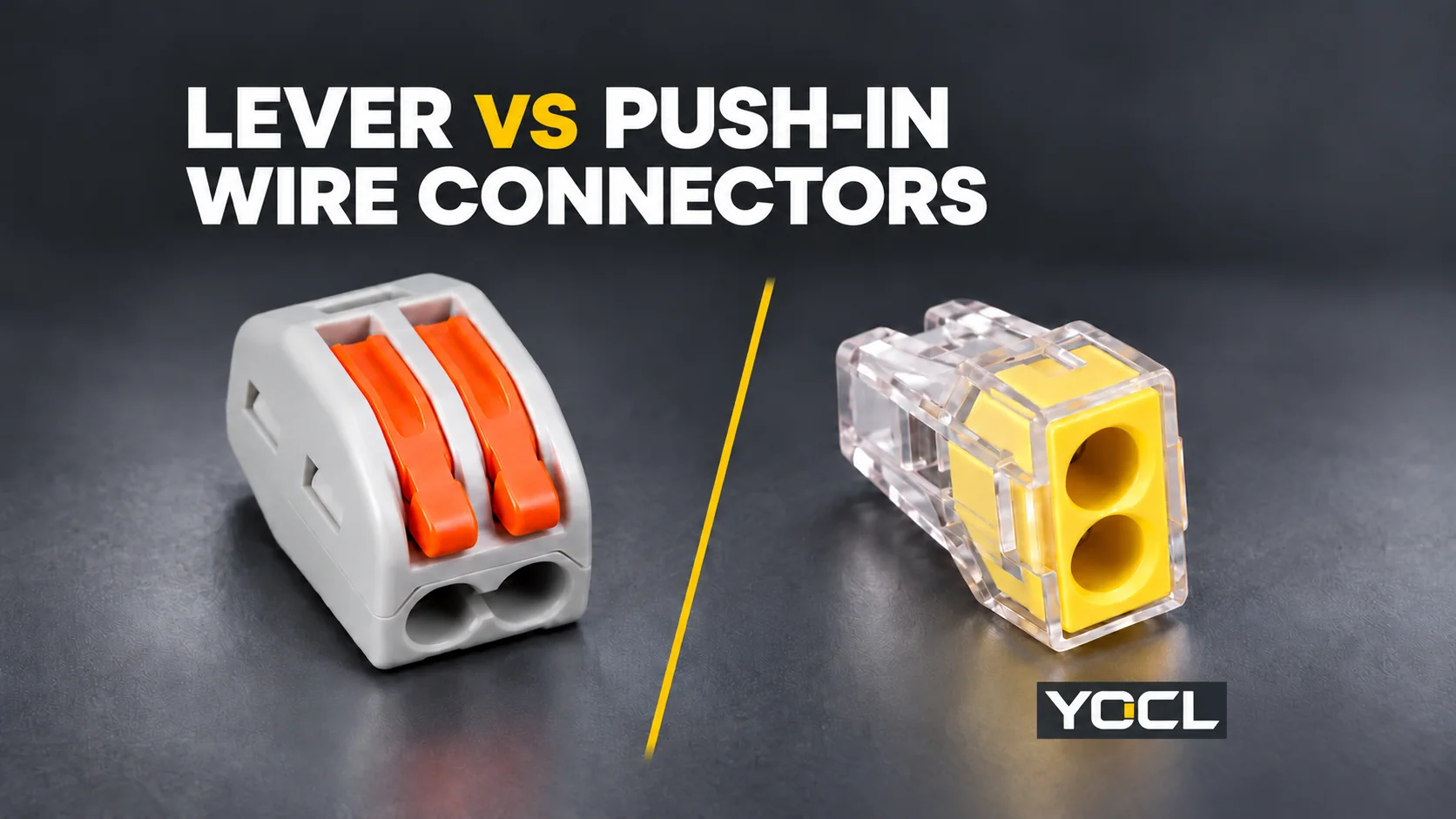
Choose a lever connector when its documented conductor range covers your wire and access to the clamp matters. Choose a direct push-in connector when its specified conductor construction can be inserted directly. Solid wire may suit either; stranded and fine-stranded wire need explicit model acceptance. The actuator alone never proves compatibility.
In this comparison, push-in means a direct-insertion entry without a lever. Some catalogues use the term more broadly for spring connections. Identify the actual entry operation before comparing the conductor data.
Choose by the Conductor You Actually Have
Compare both options against the same wire specification, not against the largest number printed for either family.
| Conductor or requirement | Lever connector candidate | Direct push-in candidate | Decision boundary |
|---|---|---|---|
| Solid conductor | Suitable if the exact model lists that material and size | Suitable if the exact entry lists that material and size for direct insertion | Either can qualify; compare body space and required access after acceptance is established. |
| Stranded conductor | Check the permitted strand construction and its own range | Check explicit stranded-wire acceptance and insertion requirements | “Stranded” does not automatically cover every flexible construction. |
| Fine-stranded or flexible lead | Look for explicit acceptance of the bare flexible end; lever actuation provides a way to open the clamp | Requires explicit acceptance of that prepared end and its insertion method | Start with a documented flexible-wire model, rather than infer acceptance from a spring connection. |
| Ferruled stranded end | Check permission for the finished ferrule arrangement | Check permission for the finished ferrule arrangement and direct insertion | A ferrule is a separate preparation case, not automatic conversion to an accepted solid wire. |
| Frequent disconnection required | A documented lever-release arrangement may suit the access requirement | Requires its own documented release and reuse conditions | Select for the stated operation; no mechanism establishes unlimited reuse. |
The public scope of UL 486C, Splicing Wire Connectors separates conductor materials and strand configurations, including additional configurations identified by marking. That supports checking the actual acceptance record; it does not certify a YOCL connector or make one style universally suitable.
For the wider connection-method and circuit-layout map, use the wire connector guide. This page focuses on choosing between the two entry operations for a known conductor.
What the Lever Changes—and What It Leaves Open
A lever gives access to the conductor clamp through an actuator. A direct-insertion entry takes the specified prepared conductor into its clamping path. These are observable operating differences within the YOCL wire-connector range.
The practical distinction matters when an end cannot be treated as a rigid insertion piece. Opening a clamp with an actuator and pushing an end directly into an entry are different operations. However, available access does not prove that the contact accepts the conductor’s metal, strand construction or preparation.
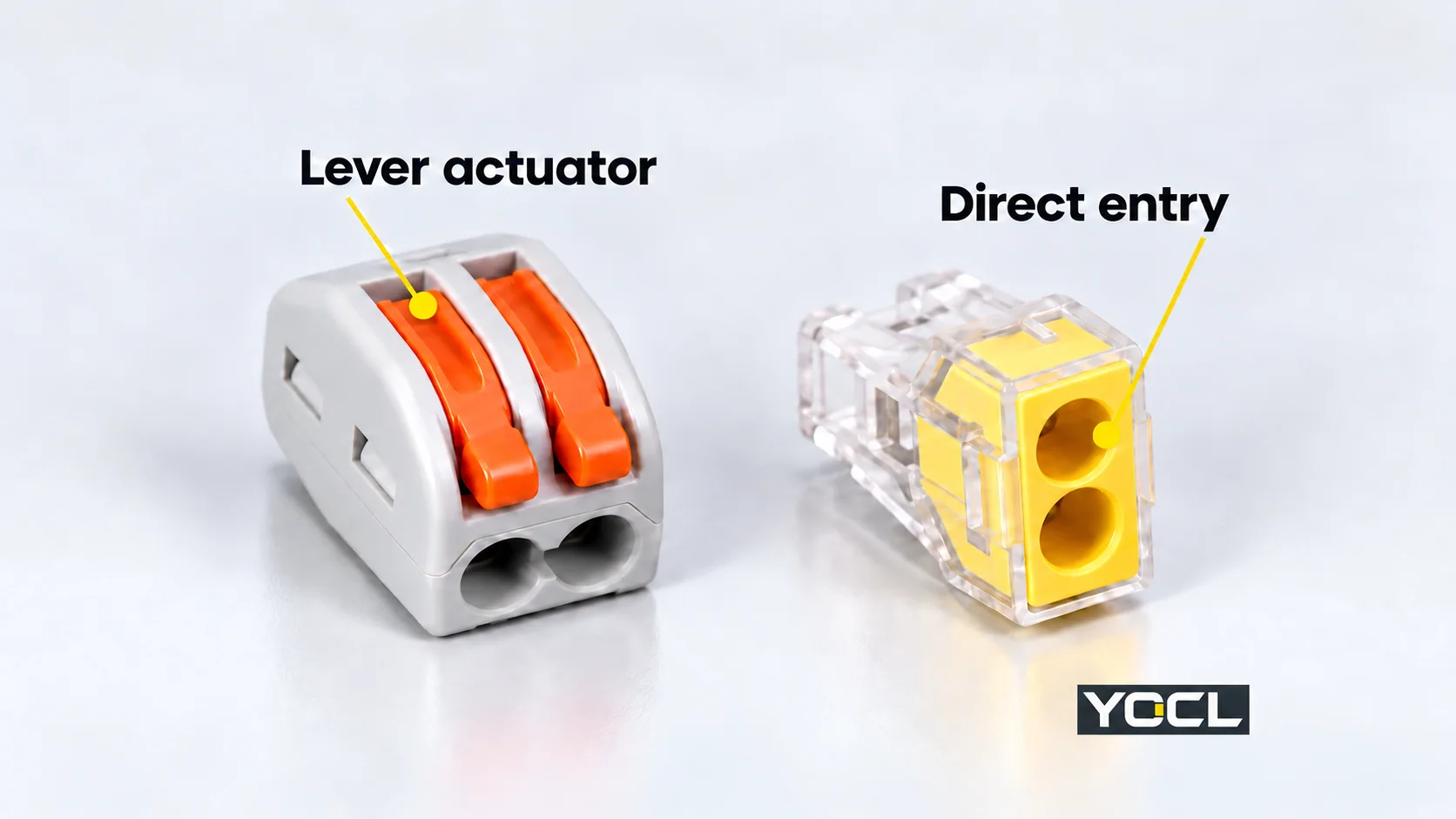
Avoid turning the comparison into “lever is always stronger” or “push-in is always faster.” Mechanical endurance, connection performance and installation time require matched evidence. None follows from the presence of an orange actuator or a transparent body.
Read the Class-Scoped Range, Not the Family Maximum
Actual YOCL records show why a single capacity headline can be misleading:
| YOCL record | Published conductor code | Published cross-section |
|---|---|---|
| 222-41x lever series | s+f-st | 0.08–2.5 mm² |
| Same 222-41x record, separate entry | f-st | 0.08–4 mm² |
| 773-10x direct-entry series | st | 1.5–2.5 mm² |
| 773-60x direct-entry series | s+st | 1.5–4 mm² |
The catalogue codes are reproduced exactly. Confirm the applicable code legend and supplied conductor definition before assigning your wire to a row; do not treat these short labels as interchangeable with every strand class.
The separate 4 mm² entry in the 222 record must not become “all conductor types from 0.08 to 4 mm².” Likewise, the 773-60x upper limit cannot be transferred to the 773-10x record. Neither the lever nor the shared series prefix resolves those distinctions.
If your conductor is 3 mm², for example, its size exceeds the 773-10x published interval but lies within the 773-60x interval. That identifies which area record to investigate; it still leaves construction, preparation and exact-model acceptance to confirm.
Equal Area Ranges Can Leave Different Questions Unanswered
Compare two further records on the same basis:
| YOCL family | Entry format | Listed area range | Listed strip length | Public class breakdown |
|---|---|---|---|---|
| PCT-252 series | Compact direct-entry format | 0.5–4 mm² | 10–12 mm | Not specified |
| PCT-412 series | Compact lever format | 0.5–4 mm² | 11–12 mm | Not specified |
The equal area ranges do not establish equal acceptance of solid, stranded, fine-stranded or ferruled ends. Request the missing construction-specific data for the exact supplied model. The different strip-length fields also show why preparation cannot be copied from a connector of similar size.
These are model-family catalogue declarations, not a universal preparation instruction. Their AWG entries, where supplied, are separate catalogue references rather than exact conversions from mm². Conductor area also does not describe the insulated wire’s outside diameter.
Check Bare and Ferruled Ends Separately
A solid conductor consists of one conducting wire. A stranded conductor contains several strands; fine-stranded constructions use finer strands and require their own acceptance information. Record the cable manufacturer’s construction designation rather than relying on the word “flexible” alone.
A crimped ferrule changes the end presented to the receiving connection. Its finished shape and dimensions need to fit the clamp, while the ferrule itself must suit the conductor and preparation tooling. Acceptance of bare wire does not establish acceptance of that ferruled end.

Use the wire ferrule guide to separate conductor-to-ferrule fit from ferrule-to-terminal fit. For this comparison, the decisive question is whether the selected receiving entry permits the complete prepared arrangement, including its range and end dimensions.
Joining a solid supply wire to a flexible equipment lead needs two acceptance checks—one for each entry. A connector may have different requirements on its two sides. A permitted supply-side wire does not automatically qualify the equipment-side lead, or vice versa.
Confirm Preparation and Access Before Substitution
Treat removal and reuse as part of the required operation. A lever may provide access for release, but the exact instruction must still define the permitted procedure and reuse conditions. A plain push-in connector must not be assigned a generic twist-and-pull removal method from another series.
IEC 60998-2-2:2002 addresses separate screwless-type connecting devices for household and similar low-voltage circuits. Its public scope helps identify a standards family; it does not provide a blanket wire range or ferrule permission for all spring connectors. An “IEC” catalogue reference without a specific model document is not proof of certification.
Once conductor acceptance is established, also confirm the same model’s current/voltage framework, continuity arrangement, enclosure conditions and physical access. Equal wire ranges cannot establish electrical or dimensional interchangeability, including across brands with similar model numbers.
Make the Final Choice from a Per-Entry Record
For each connection point, record:
- Conductor: metal, solid/strand construction designation and cross-section.
- Prepared end: bare or ferruled; relevant finished dimensions when ferruled.
- Acceptance: exact model, applicable entry/side and matching conductor row.
- Operation: specified preparation, insertion, release/reuse conditions and available actuator access.
Choose lever when its documented acceptance covers every required end and its actuation suits the access/disconnection requirement. Choose direct push-in when every required end has documented direct-entry acceptance and the release requirement is satisfied. Either remains possible when both pass those same checks. Neither is established when conductor construction or prepared-end permission is missing; resolve that gap before substituting a part.
For a review against the YOCL Wire Connectors catalogue, send this per-entry record with the required circuit arrangement, electrical/environmental conditions and quantities. A wire-size-only request leaves the central compatibility question unresolved.
References
- UL Standards & Engagement — UL 486C: Splicing Wire Connectors, edition 8, published June 30, 2023, revised February 21, 2025; public scope §§1.1–1.5, particularly material/strand configurations. Full paid requirements not consulted.
- YOCL product information — 222-41x Series Lever Wire Connectors; exterior reference and separate code-scoped conductor entries.
- YOCL product information — 773-10x Series Wire Connectors; exterior reference and published st entry.
- YOCL product information — 773-60x Series Wire Connectors; s+st entry and its own cross-section range.
- YOCL product information — PCT-252 Series Compact Wire Connectors; area/preparation declarations and missing class breakdown.
- YOCL product information — PCT-412 Series Compact Lever Wire Connectors; area/preparation declarations and missing class breakdown.
- IEC — IEC 60998-2-2:2002, edition 2.0, December 18, 2002; official public scope for separate screwless connecting devices. Full standard not consulted.