
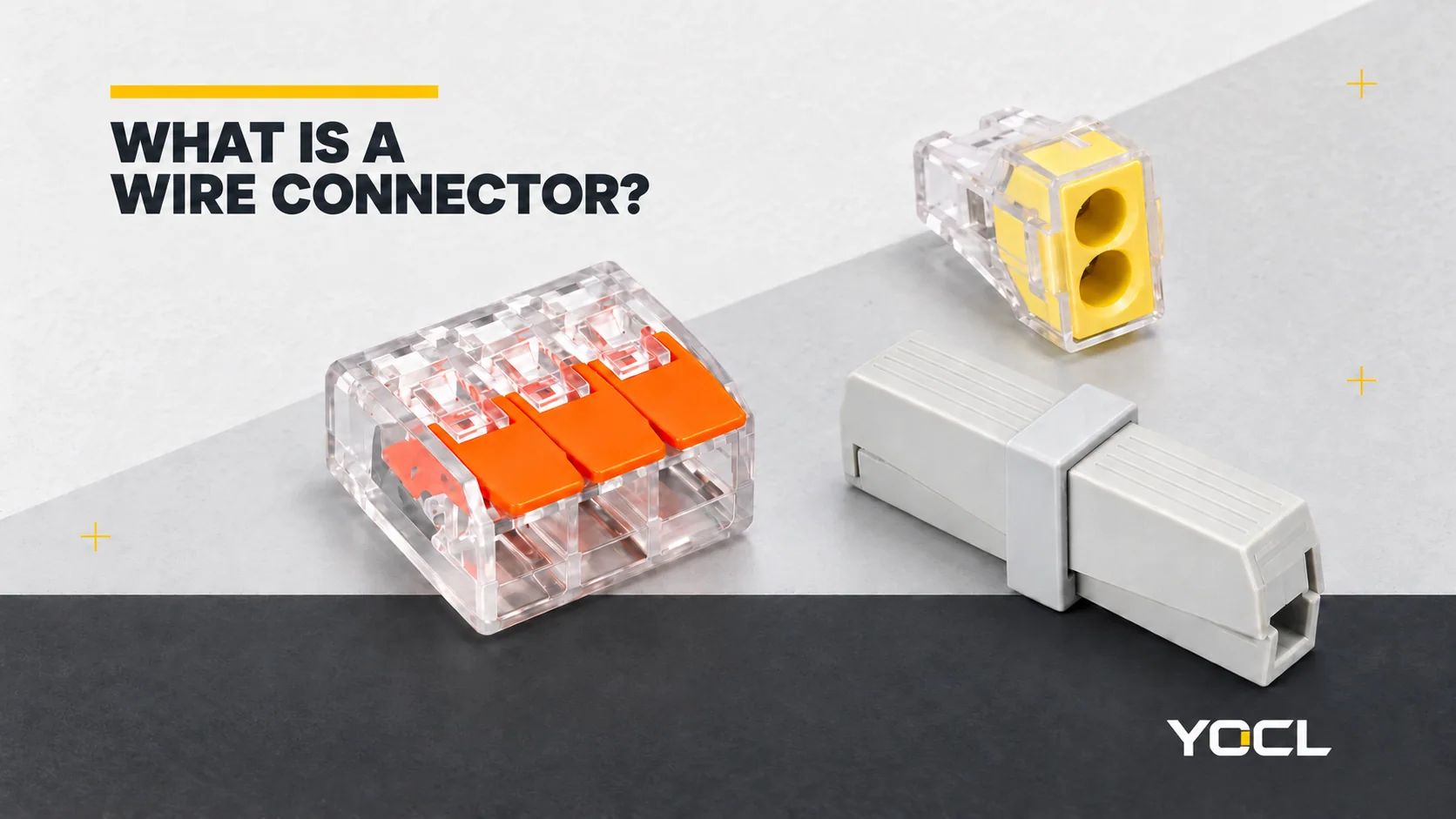
A wire connector establishes a retained conductive connection between wires, or between a wire and an equipment terminal. Its clamp or contact holds the permitted conductor, while the connection arrangement determines which points share electrical continuity. Clamping method, conductor compatibility and circuit layout are separate questions; counting the holes does not resolve them.
An ordinary joining connector does not switch the circuit or provide overcurrent protection. Fuse-terminal and other special-function versions need their own circuit and component information. This guide focuses on wire joining and equipment connections, rather than data plugs or an installation procedure.
Separate the connection method from the body format
Start with how the conductor is retained. The public scope of UL 486C, Splicing Wire Connectors identifies spring-action, twist-on, insulation-piercing or displacement, tool-applied crimp and mechanical set-screw examples. These are different connection mechanisms within that standard’s single-polarity splicing scope.
| Connection family | What establishes the connection | Useful distinction |
|---|---|---|
| Lever-operated spring | A lever actuates the conductor clamp | A lever describes operation, not universal wire acceptance or reuse permission. |
| Push-in spring | An eligible prepared conductor enters the clamp directly | Direct insertion depends on the specified conductor; release may use a separate operation. |
| Screw-operated | A screw-operated clamping arrangement secures the conductor | Preparation and tightening belong to the exact connection design. |
| Crimp splice | The specified tool forms a metal sleeve around the conductors | Sleeve, conductor combination and tooling must be matched together. |
| Twist-on | A twisting action engages the conductors in the connector | Capacity depends on the approved wire combination, rather than cap colour alone. |
| Insulation-piercing or displacement | The contact engages the conductor through its insulation | Wire construction, insulation and contact geometry need their own compatibility data. |
Next identify the body format. “Inline” describes an end-to-end arrangement; “lighting” describes a connection use and its entries; “mounted” describes how the body is supported. None replaces the clamping-method description. A lighting connector can use different entry operations on its two sides.
For a panel system, the terminal-block guide explains supported terminal assemblies, circuit functions and accessories. A connector’s mounting bracket does not make its accessories interchangeable with a modular DIN-rail terminal system.
Read conductor construction before the size range
Conductor size and construction are separate fields:
- Solid: one conducting wire.
- Stranded: several strands form the conductor.
- Fine-stranded or flexible: a finer-strand construction that needs explicit acceptance by the connection device.
Two conductors marked 1.5 mm² can have different constructions. The area designation describes conducting cross-section, not the outside diameter of the insulated wire or permission to use it in a particular clamp. A catalogue word such as “stranded” should not be extended to every fine-stranded class.
UL 486C’s public scope distinguishes conductor materials, sizes and strand configurations, including additional configurations indicated by markings. Use the selected connector’s actual acceptance data. A broad family name or a wire that physically enters the opening is insufficient.
Check the conductor metal as well. Copper, aluminium and copper-clad aluminium are distinct acceptance cases; a copper connection does not establish permission for aluminium or a mixed-metal joint. The exact model’s markings and documentation must identify the intended material or combination.

One connector can have different entry capacities
YOCL’s 224-101 / 224-201 lighting connector information lists the two sides separately:
| Connection side | Declared cross-section | Catalogue conductor code |
|---|---|---|
| Power supply | 1.0–2.5 mm² | s |
| Lighting fixture | 0.5–2.5 mm² | s + f-st |
The codes are retained as published; the applicable conductor definitions must accompany model selection. The fixture-side lower value must not be copied to the supply entry. A 0.75 mm² conductor lies within the published fixture-side size interval but below the supply-side minimum; that size comparison alone still does not establish construction compatibility.
The YC-T branch connector record provides another explicit distinction: its branch range is 0.2–4 mm² for solid and 0.2–2.5 mm² for stranded conductors. Main-line T-part configurations have separate ranges. The solid-wire upper value cannot be transferred to stranded branch wire or used as the main-line specification.
A ferrule is a further preparation choice, rather than a universal remedy for unsupported wire. The receiving connector must permit the finished ferruled arrangement. The wire-ferrule guide explains the conductor-to-sleeve and sleeve-to-terminal interfaces.
Count electrical paths, not just openings
Commoned entries share one electrical node. Isolated connections remain separate within the connector assembly. The following examples describe continuity, without prescribing a powered installation:
| Conceptual arrangement | Openings in the example | Electrical relationship |
|---|---|---|
| Common splice | Four | All four points belong to one node. |
| Inline pair | Two | The two ends form one connection path. |
| Three isolated pairs | Six | Each input joins its corresponding output; the three paths remain separate. |
Six openings could therefore describe one common six-entry splice or three isolated two-entry paths. A body photograph cannot prove which arrangement is inside. Nor does an actuator for every opening imply an electrically independent circuit for every actuator.
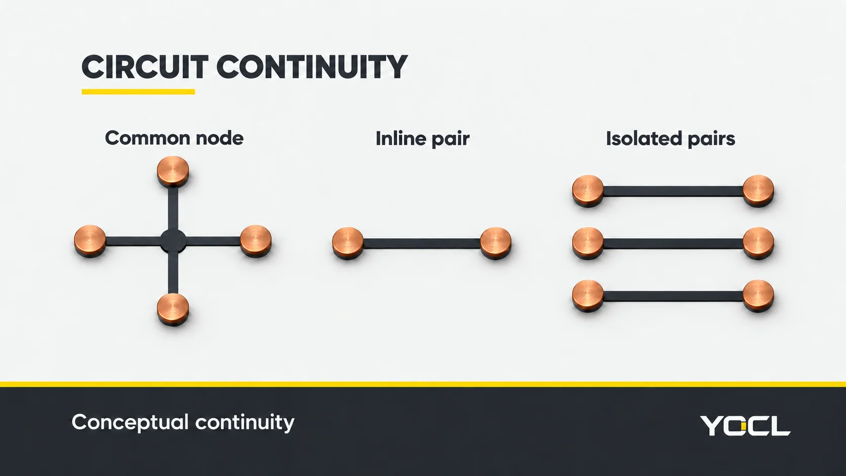
This matters when separate potentials must stay separate. Connecting them to one common node would join them electrically. Use the equipment schematic and the connector’s continuity drawing to assign connection points.
YOCL’s PCT-412 series record shows individual lever controls but explicitly states that its supplied data does not include an electrical continuity diagram. Its catalogue P designation therefore cannot establish the number of isolated circuits. Likewise, the LT-22 / LT-33 / LT-24 / LT-36 inline record retains P designations without establishing isolated-circuit count. Request the relevant diagram before assigning either family to a circuit layout.
What a rating or enclosed body leaves unresolved
Current, voltage, conductor range and operating temperature must belong to the same selected model and rating framework. A connector rating does not determine the permissible current of the complete circuit. A withstand-voltage test value also must not replace the operating-voltage rating.
The preparation requirements remain model-specific: permitted wire end, strip length, conductor count per clamping point, actuation, removal and reuse. Multiple openings do not authorize multiple wires under one clamp. This overview supplies no universal strip length or tightening instruction.
An enclosed-looking housing does not establish waterproof performance. Mounting, strain relief, enclosure conditions and any sealed mating interface need their own documentation.
IEC 60998-2-2:2002 addresses separate connecting devices with screwless-type clamping units for household and similar low-voltage circuits. UL 486C has its own splicing scope and exclusions. Those public descriptions help identify the appropriate evidence; neither establishes certification or suitability of a YOCL model for a particular assembly.
Follow the question to the right document
| Question still open | Next resource |
|---|---|
| Which compact, inline, lighting or mounted format is available? | YOCL wire-connectors range and the complete model code |
| Can this wire enter this specific clamp? | The model’s conductor material, construction, size and preparation data, separated by entry where necessary |
| Which connection points share continuity? | The exact connector circuit drawing and equipment schematic |
| Do I need a crimp sleeve joining cable ends? | YOCL cable-splice connector range and its matched conductor/tooling information |
| Do I need a sealed cable-to-cable or cable-to-panel mating assembly? | YOCL waterproof connector range and the exact mating, seal and cable specifications |
For a model enquiry, send the conductor size and construction for each entry, the required common or isolated connections, electrical and environmental requirements, mounting space and quantities. A connection sketch is particularly useful when opening count could describe more than one circuit arrangement.
References
- UL Standards & Engagement — UL 486C: Splicing Wire Connectors, eighth edition, June 30, 2023, revised February 21, 2025; public scope §§1.1–1.5 only.
- YOCL product information — 224-101 / 224-201 Lighting Wire Connectors; side-specific conductor entries.
- YOCL product information — YC-T No-Strip Branch Wire Connectors; separate main-line configurations and branch conductor ranges.
- YOCL product information — PCT-412 Series Compact Lever Wire Connectors; exterior reference and limits of supplied circuit information.
- YOCL product information — LT-22/LT-33/LT-24/LT-36 Inline Connectors; format and catalogue-designation boundaries.
- IEC — IEC 60998-2-2:2002, second edition, December 18, 2002; official public scope only.