
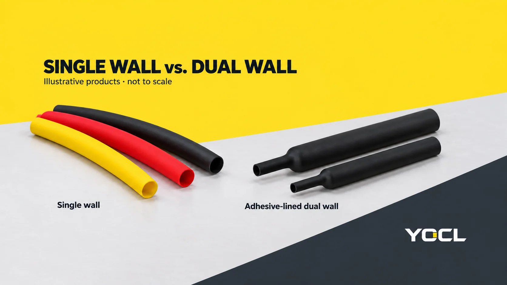
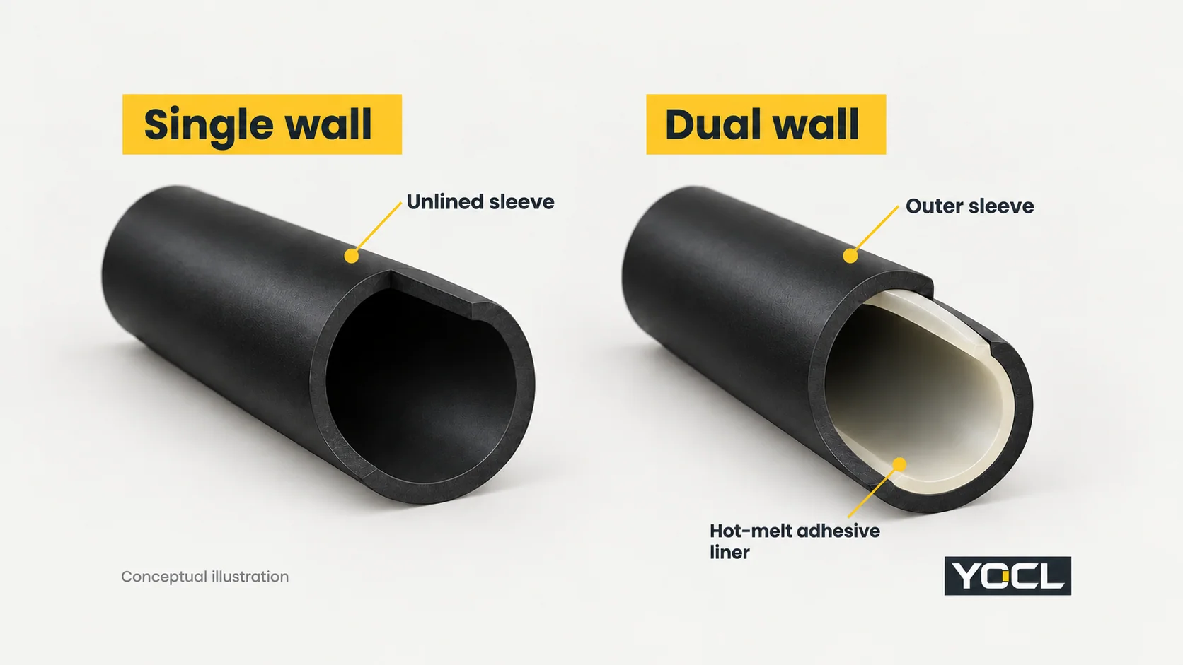
The main difference between single wall and dual wall heat shrink tubing is the inner layer. Single-wall tubing provides an unlined insulating sleeve. Adhesive-lined dual-wall tubing adds a hot-melt inner layer that bonds to compatible surfaces during installation, making it a candidate when the connection needs an environmental seal.
Choose single wall for insulation, identification and covering where an adhesive seal is unnecessary. Choose adhesive-lined dual wall when sealing the tubing-to-cable interface is part of the job. Then check the actual product’s dimensions, material, recovery conditions and service requirements. The number of layers alone is not a complete specification.
This comparison concerns unlined single-wall tubing and adhesive-lined dual-wall tubing for electrical wiring. “Dual wall” here describes that construction, not a guarantee that every two-layer product has identical properties.
Single wall vs. dual wall: the practical differences
| Comparison point | Single-wall heat shrink | Adhesive-lined dual-wall heat shrink |
|---|---|---|
| Construction | An insulating sleeve without an internal adhesive layer | An outer sleeve with a hot-melt adhesive inner layer |
| Main reason to choose it | Covering, electrical insulation or identification without a bonded seal | Bonding and sealing at compatible cable or component interfaces |
| How it retains its position | Recovery brings the sleeve into mechanical contact with the underlying part | Recovery provides contact while the heated liner flows and bonds |
| Moisture-sealing decision | A close fit alone does not establish a sealed joint | A useful candidate when the selected liner and installed arrangement can meet the sealing requirement |
| Diameter selection | Must pass over the largest feature and recover onto the smaller surface | The same fit checks apply; also verify the permitted sealing/contact range |
| Finished size and flexibility | Compare the actual wall, material and installed geometry | Compare total wall, liner and installed geometry; layer count is not a universal stiffness ranking |
| Thermal process | Follow that product’s recovery requirements | Follow the requirements for both outer-sleeve recovery and adhesive activation |
| Electrical and environmental ratings | Check the exact grade and application evidence | Apply the same check; adding adhesive does not automatically establish voltage, UV or fluid resistance |
The adhesive construction is also recognized in the official scope of IEC 60684-3-248:2007, which describes dual-wall polyolefin sleeving with adhesive inner walls. That scope identifies a product family; it does not certify a particular tubing model.
What the adhesive layer changes
A single-wall sleeve can fit closely around a wire, terminal or splice without bonding to it. That is useful when the required function is covering the part rather than closing a moisture path at the sleeve ends. For example, colour identification inside a protected control panel does not necessarily require an adhesive liner.
In adhesive-lined tubing, heating performs two jobs: the outer sleeve recovers toward the underlying shape, and the inner material softens and flows at the mating surfaces. With compatible materials and the specified process, that liner can form the bond needed for sealing. This makes the interface, rather than simply the outside appearance, the important difference.
For a joint between two cables, consider where the tubing lands on each cable jacket. For a transition between a cable and a larger component, consider both mating surfaces. A liner needs a suitable surface and sufficient contact; a tube that looks tight at its widest point may still leave an unsuitable transition elsewhere.
An independent example appears in the U.S. Navy’s MIL-STD-2003-1B, Appendix 1A, Figure 1A7. Its specified cable methods distinguish adhesive moisture-sealing tubing from uncoated identification tubing and address surface preparation and adhesive flow. These are shipboard methods, not installation instructions for every YOCL model, but they show why the bonding process matters.
Does dual-wall tubing make a connection waterproof?
Adhesive-lined tubing can be part of a moisture-sealing arrangement. The result still depends on the selected product, compatible surfaces, geometry, installation and exposure. A useful specification states whether the joint must tolerate condensation, splashing, washdown or immersion, rather than asking only for “waterproof heat shrink”.
For an ingress-protection requirement, obtain evidence for the relevant completed arrangement. IEC 60529 classifies protection provided by enclosures; a dual-wall description by itself does not assign an IP rating to a splice or to the equipment around it.
Which type fits your application?
Start with the function the sleeve must perform. “Indoor” and “outdoor” are useful context, but the actual exposure at the joint is the better decision input.
| Application condition | Starting choice | What decides the final choice |
|---|---|---|
| Wire identification or covering in a dry, protected panel | Single wall | Suitable dimensions, electrical duty and material grade |
| A protected terminal or splice needs insulation, with no bonded environmental seal required | Single wall | Required coverage, wall build and the equipment’s insulation requirements |
| A joint needs a bonded seal against the specified moisture exposure | Adhesive-lined dual wall | Liner-to-jacket compatibility, contact geometry and evidence for the required exposure |
| An outdoor cabinet protects the wiring, but condensation may reach the joint | Assess whether a local seal is required; dual wall is a candidate if it is | Actual condensation path and equipment design, rather than outdoor location alone |
| A vehicle or machine connection is exposed to fluids | A qualified tubing/sealing system | Compatibility with the named fluid, temperatures and connection surfaces; either construction needs supporting data |
| A cable repeatedly flexes or carries mechanical tension at the covered point | Review the cable support and connection design first | A flexible-looking sleeve does not establish suitability for repeated flexing or replace the required mechanical restraint |
These are starting choices, not substitutes for the equipment specification. For demanding fluids, immersion or movement, the correct answer may be a differently qualified connection system rather than either general-purpose tubing type.
A real YOCL comparison: the same 3:1 ratio, different construction
Shrink ratio does not identify the liner. Two products can both be described as 3:1 yet provide different interfaces and wall constructions.
The current YOCL catalogue provides a concrete example: 3:1 Zero-Halogen single-wall tubing and HS3X 3:1 adhesive-lined dual-wall tubing.
| Published catalogue field | 3:1 Zero-Halogen single wall | HS3X 3:1 dual wall |
|---|---|---|
| Size entry compared | 12.0/4.0 mm | 1/2 inch / 12.7 mm |
| Minimum supplied inside diameter | 12.0 mm | 12.7 mm |
| Maximum inside diameter after recovery | 4.0 mm | 4.2 mm |
| Internal adhesive | None | Hot-melt adhesive |
| Published wall field | “Wall after recovery”: 0.70 ± 0.15 mm | “Total Wall Thickness”: 1.65 ± 0.30 mm |
| Separately listed adhesive thickness | Not applicable | 0.50 ± 0.20 mm |
These are YOCL catalogue declarations, not results of an independent comparison test. The wall fields retain their original names: the single-wall page explicitly says “after recovery”, while the HS3X total-wall heading does not state its measurement condition. Confirm the measurement basis before comparing thickness quantitatively, and do not add the separately listed adhesive thickness to a value labelled “total”.
The useful decision is already visible: the ratio and approximate size do not tell you whether the product has an adhesive layer. Select the required construction, then check the model’s actual dimensions and the space available around the finished joint.
A diameter screen with explicit inputs
Suppose a round connection has a 10 mm largest feature that the tubing must pass over, and a 5 mm cable jacket where it must recover. These are illustrative dimensions, not a verified installation.
Two basic checks are:
- The supplied inside diameter must clear the largest feature.
- The fully recovered inside diameter must be smaller than the surface it needs to grip.
NASA’s KSC-E-165 Revision F, section 3.8.1.1.1 uses this dimensional relationship in its ground-support-equipment fabrication requirements.
| Preliminary check | Single-wall entry | HS3X entry |
|---|---|---|
| Supplied diameter clears 10 mm | 12.0 > 10 mm | 12.7 > 10 mm |
| Maximum recovered diameter is below 5 mm | 4.0 < 5 mm | 4.2 < 5 mm |
| Basic diameter screen | Passes | Passes |
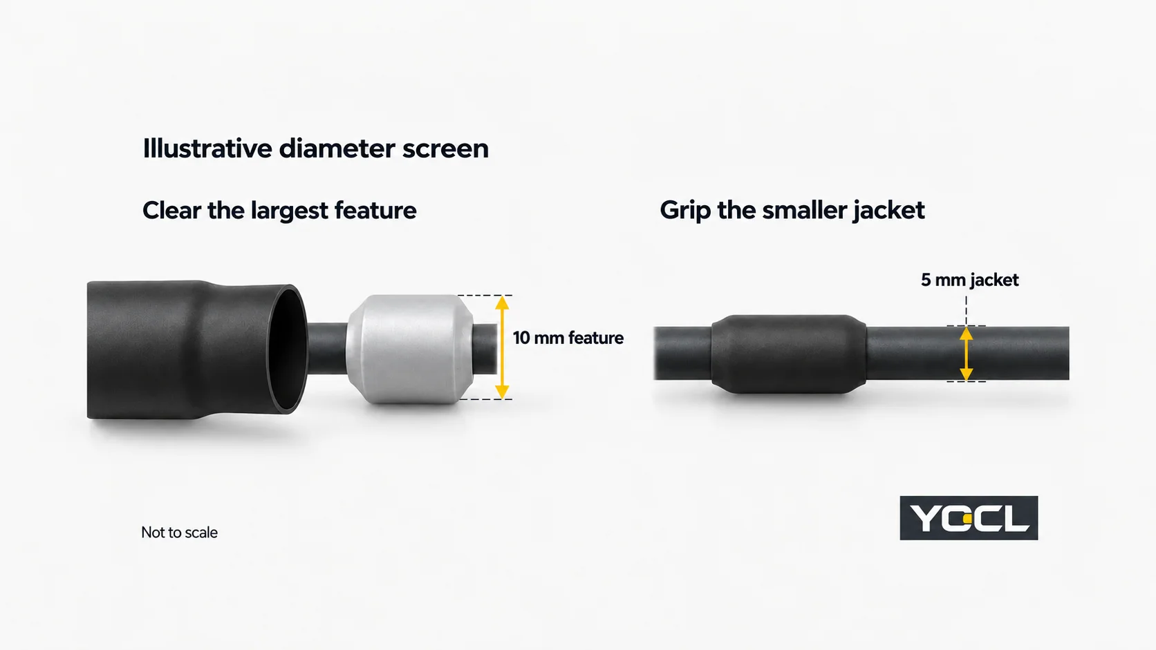
Both entries pass this screen. If the task is protected insulation without a bonded seal, the single-wall construction can remain a candidate. If a bonded moisture seal is required, assess HS3X’s liner and application conditions.
The diameter screen does not establish sealing, electrical suitability or finished outside diameter. On a 5 mm cable, the underlying jacket prevents either sleeve from reaching its freely recovered state. Obtain the permitted application range and installed wall/build information before approving fit in a confined space.
Recovery temperature and operating temperature answer different questions
Temperature data should be compared by field, not by whichever number looks highest.
| Temperature field | Question it answers |
|---|---|
| Initial shrink temperature | At what stated temperature does recovery begin? |
| Full shrink or recovery temperature | What thermal condition is specified for full recovery? |
| Continuous operating temperature | What service-temperature range is declared for the installed product? |
For HS3X, YOCL lists an initial shrink temperature of ≥70°C, a full shrink temperature of ≥125°C, and an operating range of −45°C to +125°C. These are separate fields for that model, not general values for all dual-wall tubing. Source: HS3X technical specifications.
Heating only until the sleeve starts moving is not evidence that recovery and bonding are complete. Conversely, a recovery-temperature figure is not a heat-gun setting or a permission to expose every nearby component to that temperature. Use the chosen model’s installation process and account for the cable jacket and connection beneath it.
The same discipline applies to single wall. Its recovery and service fields must come from its own documentation; values from an adhesive-lined model cannot fill gaps in another datasheet. NASA’s section 3.8.1.1.1 likewise makes heat exposure dependent on tubing size and type and calls for avoiding damage to the covered object.
Compare electrical and environmental evidence on an equal basis
Both constructions need documentation for the actual electrical duty. A liner does not, by itself, establish a higher voltage rating; an unlined sleeve is not automatically inadequate insulation. Compare the declared grade, thickness, service conditions and applicable certification record.
UL 224, eighth edition, public scope covers extruded insulating tubing, including heat-shrinkable tubing. Its scope also addresses the need for additional features in some service conditions, including liquid exposure. This is why the chosen tubing’s actual record matters more than a generic “UL” statement.
UL’s insulating-tubing certification guidance explains that voltage, temperature and optional ratings are recorded as conditions of acceptability. Check the exact model and conditions when sunlight, oil, flame behaviour or another property matters. Neither wall count nor a general certification statement supplies all of those answers.
Also distinguish Recognized Component status from certification of finished equipment. UL’s Component Recognition explanation makes that boundary explicit: a component is evaluated for use under specified conditions within a larger product. Its recognition does not automatically certify the completed splice or machine.
For purchasing, compare quotations against the same duty: required sealing function, diameters, grade, finished space, process and documentation. A lower unit price is useful only when the product still completes the specified job; adding an adhesive liner is useful when its bonding function is actually required.
To compare YOCL options, use the heat-shrink tubing catalogue and provide the largest installation diameter, final cable diameter, jacket material, exposure and temperature requirements. That gives a defined basis for checking the model and requesting its applicable dimensions, instructions and evidence.
References
- IEC — IEC 60684-3-248:2007: General-purpose heat-shrinkable dual-wall polyolefin sleeving. Official scope summary; adhesive inner walls and construction family.
- U.S. Department of Defense / Department of the Navy — MIL-STD-2003-1B(SH), 2020. Appendix 1A, Figure 1A7; shipboard cable methods illustrating adhesive sealing and identification tubing.
- IEC — IEC 60529:1989+AMD1:1999+AMD2:2013, consolidated edition. Official scope summary; enclosure ingress-protection classification.
- YOCL product information — 3:1 Zero-Halogen Single-Wall Heat Shrink Tubing. Dimension table and declared construction.
- YOCL product information — HS3X 3:1 Dual-Wall Adhesive-Lined Heat Shrink Tubing. Dimension table, material layers and temperature fields.
- NASA Kennedy Space Center — KSC-E-165 Revision F, 2021. Section 3.8.1.1.1; diameter selection and heat-exposure considerations.
- UL Standards & Engagement — UL 224, eighth edition, 2026. Public scope for extruded insulating tubing and actual service conditions.
- UL Solutions — Insulating Tubing Testing and Certification. Tubing evaluation and conditions of acceptability.
- UL Solutions — The UL Component Recognition Classification. Component recognition and end-product certification boundary.