
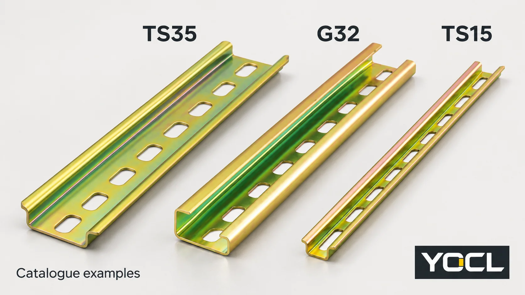
Choose the rail section and depth explicitly accepted by the device’s mounting specification. TS35 is a 35 mm top-hat family, G32 is an asymmetric 32 mm G-profile, and TS15 is a mini top-hat interface. They are different mounting geometries; the words “DIN rail,” an approximate width or a clip that appears to catch do not establish a substitute.
A device can accept more than one section when its documentation says so. The decision is therefore which profiles this particular device or documented adapter arrangement supports, rather than which rail is universally better.
Read the device declaration across the three choices
Keep the device model, mounted duty and panel requirements unchanged while comparing rails. In this table, “not established” means that the stated declaration supplies no approval for that alternative. It does not claim that every device with that description is physically incapable of another mounting arrangement.
| What the device documentation actually specifies | TS35 | G32 | TS15 | Decision |
|---|---|---|---|---|
| Only a named 35 mm top-hat section and depth | Use the named depth/configuration | Not established | Not established | Retain the stated TS35 interface |
| Only the matching G32 section | Not established | Use the specified G-profile | Not established | Retain the G32 interface and its orientation |
| Only a named TS15 section | Not established | Not established | Use the specified mini section | Retain the TS15 interface |
| Two or more profiles are explicitly listed | Candidate only where listed | Candidate only where listed | Candidate only where listed | Compare the listed options against the assembled layout and duty |
| An exact adapter arrangement is specified | Follow its accepted rail configuration | Follow its accepted rail configuration | Follow its accepted rail configuration | Check both adapter interfaces and the completed assembly |
| Only “DIN rail mounting,” with no section or drawing | Unresolved | Unresolved | Unresolved | Obtain the complete mounting requirement before choosing |
This matrix turns a mounting statement into a bounded decision. It is not a universal device-versus-rail test chart. For the broader component and accessory map, use DIN Rails Explained.
Compare the engagement geometry, not just the width
The following YOCL examples identify the sections you are comparing. These nominal values are product descriptions, not complete tolerance drawings or device approvals.
| Rail example | Geometry relevant to the mounting foot | What must match |
|---|---|---|
| 35 × 7.5 mm TS35 steel rail | Symmetric top-hat section | The device’s accepted flange arrangement and section depth |
| 35 × 15 mm TS35 steel rail | Same nominal width, deeper top-hat section | Explicit acceptance of the deeper configuration and its installed envelope |
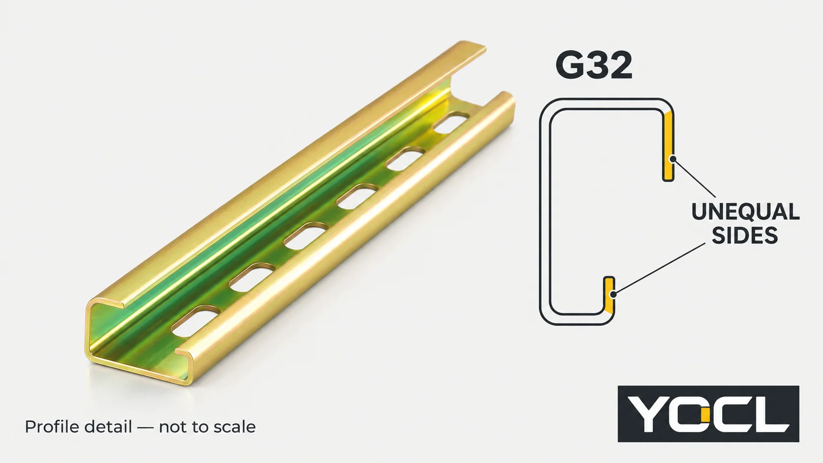
| 32 mm G-profile steel rail | Asymmetric section with different sides | The corresponding mounting-foot geometry and orientation |
| 15 × 5.5 mm TS15 mini steel rail | Smaller top-hat section | A mounting foot specified for that mini interface |
G32 changes the shape presented to the foot
G32 is not simply a TS35 rail narrowed by a few millimetres. YOCL’s G32 drawing shows unequal 15 mm and 9 mm flange projections. Those features belong to an asymmetric section and must be read with the device’s mounting geometry.
Look at the complete engagement outline and the orientation required by the drawing. One edge apparently engaging does not demonstrate that the other locating or retaining feature is seated as specified. Do not reshape a clip, add an improvised shim or force a device onto another section to overcome a mismatch.
TS15 requires its own accepted interface
TS15’s smaller top-hat form can be relevant where the equipment specifies a mini rail. A compact device body, however, does not establish a TS15-compatible foot. Conversely, a device specified for TS15 does not inherit TS35 acceptance merely because both sections are described as top-hat.
Use the device’s exact mounting designation and drawing. When a replacement changes profile family, the mounting evidence must change with it; a familiar shape is only a reason to investigate, not acceptance evidence.
Two TS35 heights are not three-profile compatibility
The YOCL SJ cage-spring terminal-block record expressly lists TH35-7.5 or TH35-15. This is a useful example of a documented two-height mounting declaration.
That statement supports those named 35 mm sections for the stated series. It supplies no declaration for G32 or TS15. Nor should its two-height acceptance be transferred to a different device whose sheet lists only one depth.
TS35 appears in the rail product names, while TH35 appears in this device declaration. Compare the full designation and relevant drawing rather than relying on the prefix alone. For detailed TS35 dimensions, thicknesses and fixing-slot variants, use the TS35 dimension reference.
If a device accepts both TS35 heights, either remains a candidate only after reviewing the installed arrangement. A deeper rail can change where the mounted device sits relative to the panel and adjacent objects. Use the actual assembly outline for wiring, cover and release access rather than assuming a uniform shift of every device feature.
An adapter adds interfaces that need their own evidence
A documented adapter can provide an alternative mounting arrangement. The word “adapter” alone does not establish which device and rail it connects.
| Interface or condition | Evidence to obtain | What remains unresolved if it is missing |
|---|---|---|
| Device to adapter | Named device reference, attachment arrangement and instructions | Whether the device can be retained by that adapter |
| Adapter to rail | Accepted rail section, depth and mounting method | Whether the adapter suits the proposed rail |
| Completed assembly | Installed outline, duty limits, fixing and service-access requirements | Whether the combined arrangement works in the panel |
The IEC 60715:2017 public preview, Introduction and Scope, distinguishes direct rail mounting from mounting through accessories and separates mounting compatibility from functional interchangeability. It does not approve a particular adapter or make two electrically different devices interchangeable. See the original IEC preview.
Do not assume that an adapter preserves protective-earthing performance or other device functions. The same preview assigns the rail’s protective-conductor role to the relevant product requirements. Any such duty needs its own evidence for the proposed assembly, beyond a mechanical fit claim.
Review what changes when the rail changes
Once the device-to-rail interface is supported, review the rest of the replacement. Keep these questions distinct from the profile-family choice:
- Panel attachment: does the selected rail configuration suit the specified fixing arrangement and receiving structure?
- Support duty: is the material, section and support layout appropriate for the mounted equipment under the applicable guidance?
- Installed access: can the device be fitted, wired, released and removed using its documented method within the available space?
- Restraints and accessories: do rail-mounted end stops accept the new section, and do device-side accessories remain matched to their device series?
A rail replacement is not permission to assign a universal screw interval, tightening torque or working load. A device staying clipped during a quick inspection also does not establish the complete support arrangement.
If a terminal row is involved, distinguish rail restraints from terminal-side bridges and end plates. The terminal-block organization guide covers that assembly task.
For physical inspection or sample evaluation in existing electrical equipment, use competent personnel and the appropriate isolated state. The UK’s Health and Safety Executive HSG85 guidance, pages 20–22, explains safe dead working. This article supplies no live fitting, removal or force-test procedure.
Record the choice and any unresolved condition
| Evidence state | Record the outcome | Next step |
|---|---|---|
| Exact device accepts the selected section and depth; assembly requirements are addressed | Supported mounting choice | Retain model, drawing and configuration references |
| Device declaration is clear, but panel/support/access questions remain | Interface supported; assembly review pending | Resolve the outstanding layout or duty evidence |
| Only a generic DIN-mounting description is available | Compatibility unconfirmed | Obtain the complete mounting-foot requirement |
| A cross-profile adapter is proposed without a complete device/rail schedule | Adapter arrangement unconfirmed | Identify both interfaces and their applicable instructions |
| Part identity, drawing or fit observations conflict | Hold for review | Resolve the conflict without modifying the clip or rail to force engagement |
For a new panel, choose among the profiles that the selected equipment actually supports. For a retrofit, retain the documented interface unless the replacement arrangement has its own supporting evidence. Multiple accepted profiles create options; they do not remove the assembly checks.
Send the device model and mounting declaration, existing and proposed rail drawings, any adapter reference and panel layout through the YOCL DIN rail range for a configuration review. Identify whether you are confirming a like-for-like replacement, changing TS35 depth or changing profile family so the remaining question is explicit.
References
- YOCL product information, 35 × 7.5 mm Slotted Steel DIN Rail—shallow TS35 section description and exterior image; checked November 2, 2026.
- YOCL product information, 35 × 15 mm Slotted Steel DIN Rail—deeper TS35 section description; checked November 2, 2026.
- YOCL product information, 32 mm Steel G-Profile DIN Rail—asymmetric section, product drawing and exterior image; checked November 2, 2026.
- YOCL product information, 15 × 5.5 mm Mini Steel DIN Rail—TS15 section and exterior image; checked November 2, 2026.
- YOCL product information, SJ Cage Spring DIN Rail Terminal Blocks—TH35-7.5 / TH35-15 mounting declaration; checked November 2, 2026.
- IEC, IEC 60715:2017 original public preview, Introduction p. 6 and Scope p. 7—mechanical mounting and functional/protective-conductor boundaries; full paid standard not consulted.
- UK Health and Safety Executive, Electricity at work: Safe working practices (HSG85), third edition, 2013, pp. 20–22—UK dead-working guidance.