
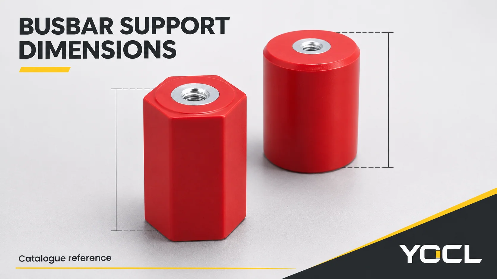
Read a busbar insulator’s height, complete body envelope and threaded interfaces together. The EN and MNS tables below provide nominal YOCL catalogue dimensions checked on November 3, 2026. Use them to identify a configuration, then obtain its applicable mounting drawing. Height alone does not establish an interchangeable part, an insulation distance or a permissible load.
EN hexagonal standoff dimensions and thread options
Source: YOCL EN hexagonal standoff insulators. Each row joins a listed body’s dimensions to one corresponding thread configuration. All values are in millimetres.
| Model | Height H | Across flats A/F | Nominal thread diameter | Published thread depth |
|---|---|---|---|---|
| EN25 | 25 | 26 | 6 | 9 |
| EN30 | 30 | 26 | 6 | 9 |
| EN32 | 32 | 26 | 6 | 9 |
| EN40 | 40 | 26 | 6 | 9 |
| EN100 | 100 | 45 | 10 | 15 |
| EN100 | 100 | 45 | 12 | 18 |
| EN110 | 110 | 45 | 10 | 15 |
| EN110 | 110 | 45 | 12 | 18 |
| EN120 | 120 | 45 | 10 | 15 |
| EN120 | 120 | 45 | 12 | 18 |
Repeated model names identify different thread configurations. Retain the selected diameter and depth with the model; do not combine fields from different rows. The nominal thread-diameter column is not a complete thread designation: the applicable form, pitch and tolerance still need confirmation.
MNS metric dimensions: choose a listed height within the group
Source: YOCL MNS metric-thread busbar insulators. The body is cylindrical. Heights are discrete listed options, not a continuous range. The final column pairs each declared metric thread option with its depth in millimetres.
| Diameter group | Body diameter φ (mm) | Listed heights H (mm) | Thread option / depth (mm) |
|---|---|---|---|
| MNS16×□□ | 16 | 20, 25, 30, 35, 40 | M6 / 8 |
| MNS20×□□ | 20 | 20, 25, 30, 35, 40 | M6 / 8 |
| MNS25×□□ | 25 | 25, 30, 40, 50 | M6 / 9 |
| MNS30×□□ | 30 | 30, 40, 50, 60 | M8 / 9 |
| MNS40×□□ | 40 | 40, 50, 60, 70, 80 | M8 / 12; M10 / 12 |
| MNS50×□□ | 50 | 40, 50, 60, 70, 80 | M8 / 15; M10 / 15 |
| MNS60×□□ | 60 | 60, 70, 80 | M10 / 15; M12 / 15 |
| MNS70×□□ | 70 | 70, 80, 90, 100, 110 | M14 / 18; M16 / 22 |
The square placeholders identify the height field in the source pattern. Specify the diameter group, one listed height and the chosen thread option together. The catalogue does not state metric thread pitches; the M designation alone does not complete the supply specification.
Diameter, across flats and height describe different directions
Height H is the axial dimension shown between the support’s end faces. Check the actual mounting datums on the selected drawing; the final busbar position also depends on the surrounding assembly.
Across flats A/F is the distance between opposite flat faces of a hexagonal body. It is not its corner-to-corner envelope. Where a nearby wall or component limits space, obtain the complete outline rather than treating A/F as the maximum width in every direction.
Diameter φ describes a circular dimension. Identify the feature to which the drawing applies it: a cylindrical body, a circular end region and a thread opening are different features. Do not substitute a hexagonal body’s A/F value for a cylindrical diameter merely because the numbers match.
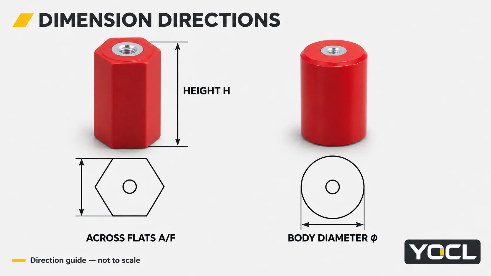
Keep these drawing directions in the enquiry. A request for “a 40 mm support” leaves open whether 40 mm means height, body diameter, an across-flats dimension or another plan-view span.
Worked lookup: EN100 has two thread configurations
Assume a drawing calls for a nominal 100 mm height and 45 mm across flats. Those inputs identify the EN100 body in the table, but leave two thread configurations:
- Nominal 10 mm thread diameter with 15 mm published depth.
- Nominal 12 mm thread diameter with 18 mm published depth.
If the required nominal thread diameter is 12 mm, retain the second configuration for review. Do not carry over the first configuration’s depth. Record the remaining thread specification, tolerances and mounting requirements as pending until confirmed in the applicable drawing.
This is a nominal lookup example, not a load test or a fastening instruction. The same body dimensions do not make the two threaded interfaces interchangeable.
Published thread depth is not an instruction for bolt length
A depth entry describes the source’s specified threaded feature. It does not by itself establish permissible fastener engagement, usable full thread or the required bolt length through a busbar and mounting stack.
Ask for the selected insert’s thread standard and pitch, tolerance or fit requirements, usable engagement limits and applicable fastening instructions. Confirm the interfaces at both ends where relevant. Avoid assuming that a bolt which starts turning has the correct thread or that it can be tightened to the full published depth.
Fastener length also depends on the parts it passes through and the engagement required by the approved arrangement. No universal subtraction rule can be established from the catalogue depth alone. Likewise, a catalogue torque-strength value is a different field from a recommended installation tightening torque; this reference assigns neither a bolt length nor a tightening value.
Similar MNS bodies can have different thread systems
The MNS imperial-thread range is a separate source. For its MNS40 group, the listed nominal thread options are 1/4 inch and 5/16 inch, with 12 mm depth. The metric MNS40 group instead lists M8 and M10 at that depth.
Matching body dimensions or a shared depth does not resolve the thread difference. Specify the thread system with the body group and height. The imperial page does not state the thread standard or pitch, so do not add an assumed thread series to the purchase record. A metric diameter conversion would not turn an imperial thread into a compatible metric thread.
Resolve a drawing conflict before accepting a fit
Compare the selected model’s dimensioned image, table and released supply drawing. Preserve the source and revision used for each field. If values disagree, keep the affected dimension unconfirmed and request a consistent approved drawing rather than selecting whichever value fits the available space.
For example, some current dimensions in the SM support page differ from its accompanying drawing image. Obtain the approved model drawing before relying on those affected rows. The EN and MNS lookups above do not resolve an SM discrepancy or establish cross-series equivalence.
Use a dimension record to make the missing information specific:
| Record field | What to retain or request |
|---|---|
| Part identity | Series, complete model/configuration, source and drawing revision |
| Axial geometry | Overall height and mounting datums |
| Plan geometry | Diameter or A/F as labelled, full envelope and fixing positions where applicable |
| Each threaded interface | Thread system, designation, pitch and required tolerance/fit |
| Insert/fastener relationship | Published depth, confirmed usable engagement and applicable mounting instructions |
| Conflicting or absent data | The exact field, competing document values and supplier response |
Nominal dimensions support a geometry screen. They do not establish the installed clearance, creepage, mechanical duty or environmental suitability. The busbar insulator overview explains those distinctions; the support-insulator selection guide develops the broader acceptance inputs.
For a drawing review through the YOCL busbar supports and insulators range, send this record with the proposed mounting arrangement and quantity. Identify whether the request concerns a new configuration, a replacement interface or an unresolved drawing dimension.
Related reading: See cracked busbar insulator inspection and YOCL resources.
References
- YOCL product information, EN Hexagonal Standoff Insulators—body dimensions, paired thread configurations and original exterior/profile references; checked November 3, 2026.
- YOCL product information, MNS Metric Thread Busbar Insulators—diameter groups, listed heights and metric thread-depth options; checked November 3, 2026.
- YOCL product information, MNS Imperial Thread Busbar Insulators—separate imperial thread options and documentation limits; checked November 3, 2026.
- YOCL product information, SM Series Busbar Support Insulators—page and drawing compared to identify unresolved dimensional discrepancies; checked November 3, 2026.