
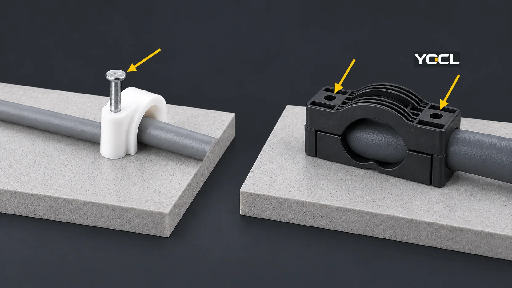
Choose a cable clip or cable clamp by the selected part’s cable contact, its fixing to the surface, and the steps needed to reach the cable later. A correctly sized nail-in clip can be a practical choice for a stable route on a suitable receiving surface. If cables will be added or replaced regularly, a holder with a documented releasable closure may reduce disturbance—but its base still needs a suitable, secure attachment. Neither the word clip nor clamp proves greater holding force, a reusable fixing, or a number of opening cycles.
That distinction matters within YOCL’s own range. Its Circle Cable Clips use a polyethylene (PE) arch and steel nail. Its K Series Cable Clamps show a central cable opening and two mounting positions, but the public record does not specify a release procedure or reuse life. A related Self-Adhesive Releasable Cable Clamp explicitly describes a thumb-tab, reusable closure; that statement does not make its adhesive pad reusable. The releasable product belongs to YOCL’s cable tie mounts selection, rather than the eight series on its cable clips and clamps landing page.
| Decision basis | Nail-in Circle clip | K Series shaped clamp | Related releasable adhesive clamp |
|---|---|---|---|
| Cable contact | Rounded PE body over an item-matched round cable | Central opening; match the selected cable arrangement to the actual drawing | Adjustable closure around the selected cable range |
| Surface fixing | Item-specific steel nail or nails into a suitable receiving surface | Two mounting positions; fastener and receiving structure must be specified | Adhesive pad; verify the bond and surface separately |
| Known access path | Nail/fixing point must be considered when planning a route change; no release/reuse instructions published | Public page does not document opening, removal or repeat use | Thumb-tab releases the closure for adding, removing or repositioning cable, according to YOCL |
| What still needs evidence | Substrate suitability, fixing retention, removal method and replacement plan | Fastener, mounting geometry, release method and any service/reuse claim | Adhesive mounting conditions and retained load; closure reuse is not pad reuse |
This is a comparison of published constructions and service information, not a laboratory ranking of holding strength. For the broader family map, including flat and tube seats and dimensional symbols, see Cable Clips and Clamps Explained. Here the question is narrower: what stays put during operation, and what has to be disturbed when maintenance reaches that cable?
Retention Has Two Interfaces, Not One Product Label
A cable holder succeeds only while the cable remains in the retainer and the retainer remains attached to its support. Consider these as two links in one load path:
cable jacket → retaining body or closure → fixing feature → mounting surface
The first link depends on the actual cable outside dimensions and profile, the contact shape, any lining, the direction of likely movement, and whether the cable can lift out of an opening. The second depends on the nail, fastener, stem or adhesive pad, plus the receiving surface and installation conditions. A close-looking cable fit cannot compensate for a loose base. An excellent base cannot compensate for a seat that lets the cable slip, pinches its jacket, or leaves an incompatible bend at the next connection.
That is why “clamp” is not a useful strength rating. A two-point mounting drawing shows where a K clamp can be attached; it does not state the installed system’s pull-out force, vibration endurance or allowable load. A nail-in Circle clip’s one- or two-nail construction also does not state a substrate-specific retention load. Compare the selected model and complete fixing arrangement, not the noun printed on the catalogue page. YOCL’s cable clips and clamps range itself calls for the retained-object dimensions and mounting surface to be checked separately and requires model-specific evidence for load or environmental duty.
Fit Should Secure the Jacket Without Damaging It
Undersized holders can pinch or distort a jacket; oversized holders can leave enough clearance for the route to move. Fit is especially easy to misjudge when an apparently similar nominal size hides a different body or fixing arrangement. Obtain the cable’s actual outside diameter, width and thickness, or tube outside diameter, including tolerances, and compare it with the selected part’s seat and item drawing. A flat cable is not correctly specified by treating its conductor cross-section as the clip’s width. A tube clamp must be matched to the tube, not to the wires inside it.
Extra compression is not a free substitute for an inadequate design. In its transport-aircraft wiring guidance, the US Federal Aviation Administration (FAA) advises appropriate clamp size and type so support does not damage insulation, and specifically warns that overtight clamping can damage coaxial cable. The FAA’s context is aircraft, not a general industrial installation rule or a test of YOCL parts. The engineering check it illustrates is still useful: ask for the applicable cable limits and the selected holder’s installation instructions before increasing pressure on the jacket. FAA AC 25.1701-1, pp. 10–12.
The Mounting Surface Can Be the Limiting Link
YOCL’s Circle item uses a steel nail; the selected size determines whether the listed item has one or two nails. A nailable surface is a prerequisite, but the nail’s presence does not establish holding force in every wallboard, timber, masonry or other substrate. The K drawing separates a central opening from two mounting positions; it does not identify a fastener material, tightening torque, approved anchor or installed load. The releasable adhesive model separates closure operation from pad bonding. Surface preparation, surface material and expected duty therefore remain independent checks. FAA aircraft guidance also warns that adhesive-supported bundle devices can loosen when their design or surface preparation is unsuitable; it is a reason to verify an adhesive installation, not a blanket rejection or acceptance of a YOCL product. FAA AC 25.1701-1, pp. 10–12.
Serviceability Is an Access, Release and Restore Test
A part may be easy to install yet difficult to service after other equipment is fitted around it. “Releasable” is also incomplete unless the installed base stays secure and the part can be returned to an approved condition. Before choosing a holder, write down the actual service event: visual inspection, removal of one cable, addition of another, or replacement of the entire route. Then trace three stages.
- Access: Can a technician reach the retaining feature and fixing point after adjacent cables, covers, enclosure walls and equipment are in place? Is there space for the needed tool and cable movement? A visible opening in a product photo is not proof of installed access.
- Release: What specifically must be moved or removed—the cable from a hook, a closure tab, a fixing nail, a separate fastener, or a complete holder? Will releasing one cable disturb neighboring conductors? If the public instructions do not describe this step, request them before treating the part as serviceable.
- Restore: Can the holder be secured again to the required condition? Check the cable seat, closure, liner if present, fixing feature, substrate and jacket. A reusable closure does not establish that a removed nail, adhesive pad or mounting base can be reused. Ask for documented replacement or reuse criteria when maintenance frequency matters.
| Planned event | The relevant access question | Why the answer may change the choice |
|---|---|---|
| Inspect without rerouting | Are cable jacket, holder and surface fixing visible after assembly? | A closed shape may retain well but hide a contact point; an accessible inspection route may matter more than nominal “quick release.” |
| Replace one cable | Can that cable be released without removing a fixing or moving neighboring runs? | A documented thumb-tab closure offers a stated release path; a nail-in or undocumented shaped part needs an exact-model procedure. |
| Add a cable | Is the new combined outside profile within the selected holder’s published range, and can it close without damage? | Opening the holder is not the same as proving the new bundle still fits or remains supported. |
| Restore after work | Is the closure, base and jacket still sound, and is the route supported as intended? | A broken feature, loose base or pinched cable can turn a convenient service step into a retention problem. |
The FAA’s aircraft maintenance guidance treats loose or damaged clamps, failed fasteners, sagging bundles, migrated cushioning and jacket chafing as inspection findings, and warns that adding wires can overload a clamp. These are examples of what to check after a route change, not stated failure rates or inspection intervals for YOCL products. FAA AC 25-27A, pp. 22–26. For ordinary equipment work, follow the applicable site procedure and the exact cable/holder instructions rather than importing an aircraft maintenance interval.
What YOCL’s Three Examples Actually Establish
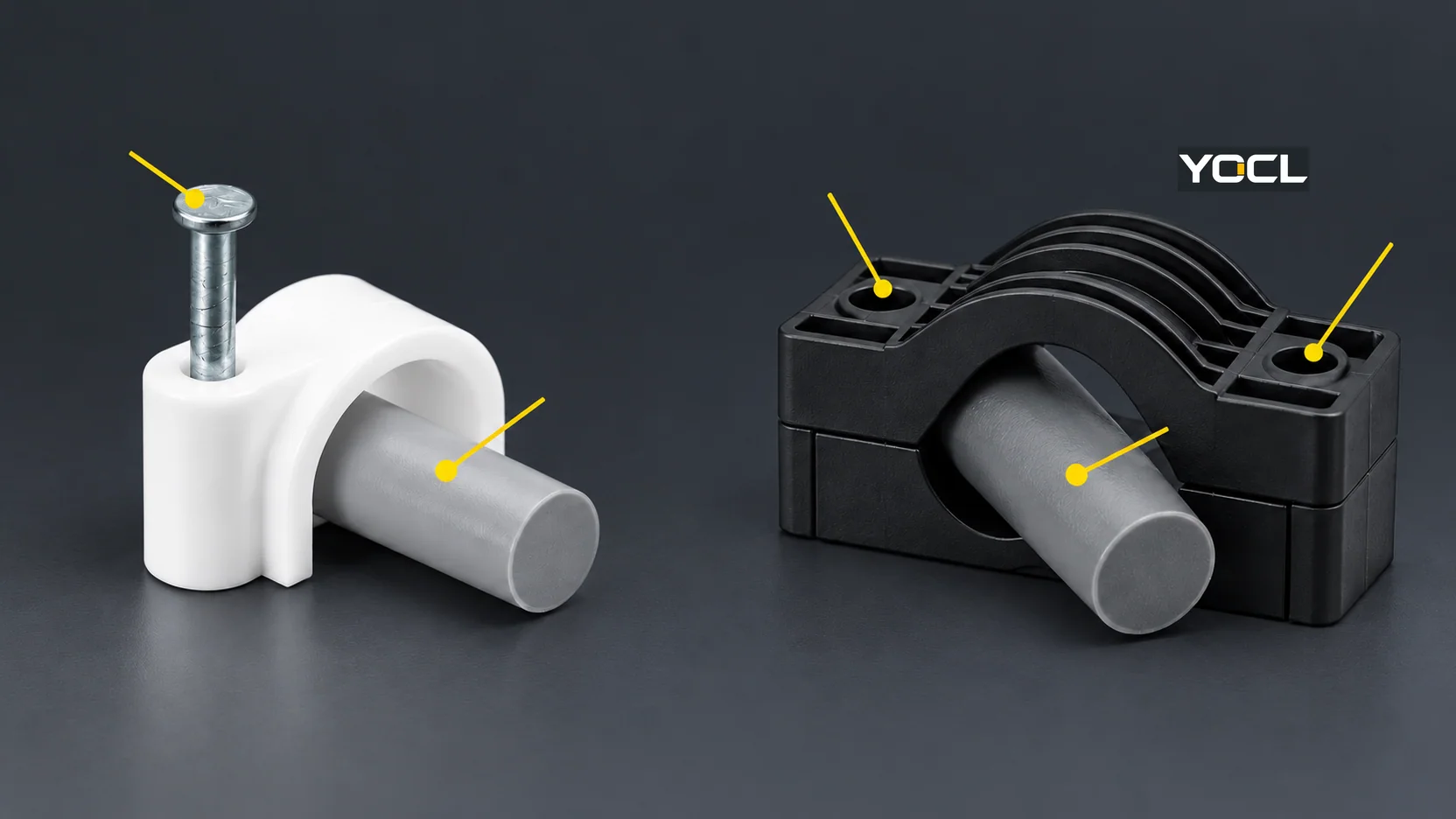
Circle clip: The Circle Cable Clips page provides a PE retaining arch, a steel nail and item-specific dimensions. It does not publish a designed release sequence or a cycle count. A stable, visible, nailable route can make this a reasonable candidate; a planned frequent cable swap creates a documentation question around removing and restoring the fixing. It is unwarranted to say that every nail-in clip must be destroyed during removal, or that the nail may always be reused.
K Series clamp: The K Series page shows a cable opening and two mounting positions with separate dimension labels. These features support a fit-and-layout comparison. They do not establish that the part hinges, splits, reopens in place, or can be repeatedly fastened. The public numerical table does not state its dimensional units, so a numeric fit should be confirmed against a complete drawing. If local cable replacement is the primary requirement, request the model’s release and reinstallation instructions before selecting it for that reason.
Related thumb-tab clamp: YOCL’s Self-Adhesive Releasable Cable Clamps expressly describe a two-stage locking closure and thumb-tab release for cable addition, removal or repositioning. That is stronger service-path evidence than a product name alone. It is an adjacent cable tie mounts product, not a listed series on the linked cable clips and clamps landing page. The wording supports closure reuse; it does not document that an adhesive pad can be peeled off and reused, or give a universal adhesive holding load. A design needing repeat service should check both the tab’s applicable instructions and the pad/substrate installation separately.
Choose Against the Actual Route and Maintenance Event
There is no universal “clip for speed, clamp for strength” answer. These are bounded starting points, each with a hold point before specification.
| Project condition | Sensible starting candidate | Hold point before approval |
|---|---|---|
| One round cable follows a stable, accessible route on a suitable nailable surface; local cable changes are uncommon | Correctly sized YOCL Circle clip | Match the exact item and cable outside diameter; verify the receiving surface and maintenance replacement plan. |
| The cable is likely to be added, removed or repositioned without disturbing adjacent runs | A model with an expressly releasable closure, such as the related YOCL thumb-tab clamp | Check selected cable range, access to the tab after assembly, closure instructions and separate adhesive-pad suitability. |
| A shaped central opening and two mounting positions suit the physical route | Evaluate the YOCL K Series drawing | Confirm dimensions and units, cable fit, fasteners, receiving structure and the release method if serviceability is required. |
| A flat cable or conduit is being compared with a round-cable holder | Start with the matching retained-object geometry, rather than the clip/clamp label | Compare actual flat width/thickness or tube outside diameter with the exact model; see the family-form overview. |
| The assembly needs a verified pull, vibration, repeat-opening or outdoor service rating | Neither generic name is enough | Obtain exact model/system evidence for the duty and installation configuration. |
Two duties make “neither” especially important. Route retention is not automatically termination strain relief. In the applicable US workplace rules, OSHA 29 CFR 1910.305 addresses cable support and protection against damage, abrasion at cabinet or box entries, and relief of pull at flexible-cord connections as distinct concerns. The precise clauses have their own scope—including temporary-wiring provisions—so do not apply them as a universal global rule. A clip along a run is no substitute for a specified cable entry, cord grip or terminal strain-relief arrangement.
High electromechanical fault restraint is another separate specification. The public abstract of IEC 61914:2021, Cable cleats for electrical installations covers cable cleats and intermediate restraints, including resistance to electromechanical forces where declared. A general routing clip or small clamp must not be assumed to be an IEC 61914 cable cleat from its shape. If short-circuit-force restraint is part of the job, use a documented cleat/system selection with the declared duty and specified mounting arrangement; this article does not establish a YOCL clip or clamp qualification.
Information to Put on the Specification or Enquiry
A useful comparison request describes the complete installation rather than asking for “a strong reusable clamp.” Give the supplier or project engineer:
- Retained object: cable or conduit type, outside dimensions and tolerances, jacket material, number of cables, and whether the route changes size along its length.
- Support interface: surface material, available fixing area, available hole layout or nailable location, and whether an adhesive attachment is permitted for the duty.
- Operating duty: cable movement, likely load direction, vibration or environmental exposure, and any required documented retention or material performance. Do not substitute a catalogue photo for test conditions.
- Service event: expected inspections and cable changes; access available after final assembly; whether one cable must be removed without disturbing others; required release, replacement and reinstallation instructions.
- Boundary condition: whether this is only route positioning, or whether the design separately needs entry sealing, termination strain relief, structural support or cable-cleat fault restraint.
Then request the exact item drawing, cable acceptance, installation method, fixing/substrate requirements and any duty-specific test or reuse documentation. The practical answer to cable clips versus cable clamps follows from that evidence: use the clip or clamp whose cable seat and surface fixing suit the route, and select a documented release path when later access is a requirement. The YOCL Cable Clips & Clamps range is the appropriate starting point for the listed series and a model-specific enquiry.
Related reading: See heavy-duty connector hood entry and clearance and cable gland thread and diameter chart.
References
- YOCL product information — Circle Cable Clips — PE arch, item-specific cable sizes and steel-nail fixing.
- YOCL product information — K Series Cable Clamps — central opening and two mounting positions; no published release or reuse procedure.
- YOCL product information — Self-Adhesive Releasable Cable Clamps — described two-stage thumb-tab closure and cable-access purpose; adhesive-pad reuse not stated.
- YOCL product information — Cable Clips & Clamps — listed families and selection factors for retained object and mounting surface.
- FAA — AC 25.1701-1, Certification of Electrical Wiring Interconnection Systems on Transport Category Airplanes (2007), pp. 10–12 — aircraft-specific support fit, insulation protection and adhesive-support cautions.
- FAA — AC 25-27A, Development of Transport Category Airplane EWIS Instructions for Continued Airworthiness (2010), pp. 22–26 — aircraft maintenance inspection examples involving clamps, fasteners and bundles.
- OSHA — 29 CFR 1910.305, Wiring methods, components, and equipment for general use — applicable US workplace wiring support, abrasion and flexible-cord connection provisions.
- IEC — IEC 61914:2021, edition 3.0, Cable cleats for electrical installations (public abstract) — cleat scope and declared electromechanical-force restraint; full paid standard not consulted.