
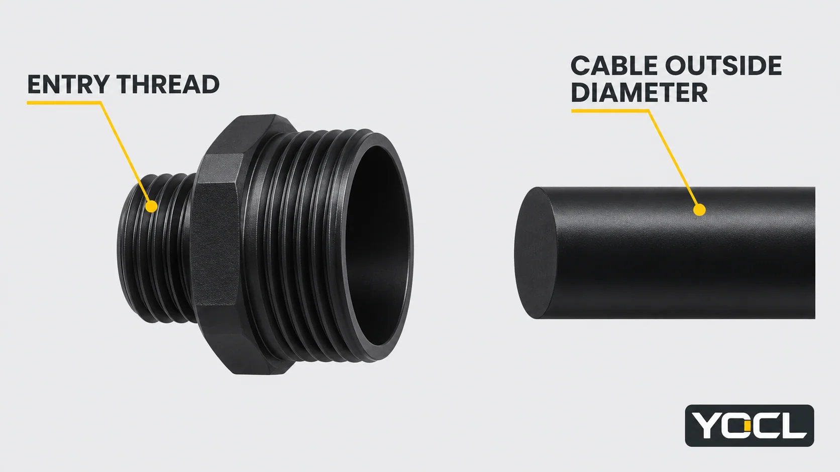
A cable gland’s entry thread and accepted cable outside diameter are separate specifications. Use the exact-model charts below: the same M20 thread can appear with different cable ranges, and an equal cable range does not make Metric, PG and NPT threads interchangeable.
These are selected YOCL catalogue configurations checked on November 4, 2026. Cable ranges are in millimetres, minimum–maximum. They apply to the listed model, rather than every gland carrying the same thread size.
Metric nylon gland size chart
Source: Divided Structure Nylon Cable Glands — Metric Thread. Keep the suffix with the range; A and B entries sharing a thread are separate configurations.
| Exact model | Entry thread | Cable OD range (mm) |
|---|---|---|
| VO-NLM12A-DS | M12 × 1.5 | 3–5.5 |
| VO-NLM12B-DS | M12 × 1.5 | 4.5–7.8 |
| VO-NLM16A-DS | M16 × 1.5 | 4–8 |
| VO-NLM16C-DS | M16 × 1.5 | 6–10 |
| VO-NLM20A-DS | M20 × 1.5 | 6–12.5 |
| VO-NLM20B-DS | M20 × 1.5 | 9–14 |
| VO-NLM25A-DS | M25 × 1.5 | 10–16 |
| VO-NLM25B-DS | M25 × 1.5 | 13–18 |
| VO-NLM32A-DS | M32 × 1.5 | 15–22 |
| VO-NLM32B-DS | M32 × 1.5 | 18–25 |
For example, VO-NLM20A-DS and VO-NLM20B-DS both list M20 × 1.5, but the second accepts a different interval rather than simply “more cable.” Its larger upper limit comes with a higher lower limit.
Metric brass gland size chart
Source: VO Metric Waterproof Brass Cable Glands. These nickel-plated brass configurations have their own published clamping ranges; do not copy a nylon variant’s range into the metal order code.
| Exact model | Entry thread | Cable OD range (mm) |
|---|---|---|
| VO-M12-NP | M12 × 1.5 | 3–6.5 |
| VO-M16-NP | M16 × 1.5 | 4–8 |
| VO-M20-NP | M20 × 1.5 | 6–12 |
| VO-M25A-NP | M25 × 1.5 | 10–14 |
| VO-M25B-NP | M25 × 1.5 | 8–16 |
| VO-M25C-NP | M25 × 1.5 | 13–18 |
| VO-M32A-NP | M32 × 1.5 | 15–22 |
| VO-M32B-NP | M32 × 1.5 | 16–20 |
The three M25 entries demonstrate overlapping alternatives. For a nominal 9 mm cable, the B row contains that diameter while A and C do not. For 17 mm, C contains the diameter while A and B do not. Check the cable’s complete dimensional tolerance before using either observation to shortlist a model.
PG brass gland size chart
Source: VO PG Waterproof Brass Cable Glands. PG labels identify the mounting thread; the cable interval remains the separate final column.
| Exact model | Entry thread | Cable OD range (mm) |
|---|---|---|
| VO-PG7-NP | PG7 | 3–6.5 |
| VO-PG9-NP | PG9 | 4–8 |
| VO-PG11-NP | PG11 | 5–10 |
| VO-PG13.5-NP | PG13.5 | 6–12 |
| VO-PG16-NP | PG16 | 10–14 |
| VO-PG25-NP | PG25 | 15–22 |
| VO-PG29-NP | PG29 | 18–25 |
| VO-PG36-NP | PG36 | 25–33 |
NPT brass gland size chart
Source: VO NPT Waterproof Brass Cable Glands. The fractional NPT labels are thread designations, not literal cable diameters. They are written here in the familiar “3/8 NPT” order without converting their meaning.
| Exact model | Entry thread | Cable OD range (mm) |
|---|---|---|
| VO-NPT3/8-NP | 3/8 NPT | 4–8 |
| VO-NPT1/2-NP | 1/2 NPT | 6–12 |
| VO-NPT3/4-NP | 3/4 NPT | 13–18 |
| VO-NPT1-NP | 1 NPT | 18–25 |
These are independent lookups, not equivalent-size rows across thread systems. If the cable range you need appears under PG or NPT, that does not make the fitting a direct replacement for an M-thread entry. Use the Metric vs PG vs NPT guide for the separate thread-identification task.
How to read the chart for a known cable and entry
Start with the enclosure’s actual entry designation, such as M20 × 1.5. Filter for that thread, then check the cable manufacturer’s minimum and maximum outside diameter against each remaining model’s range:
Gland minimum ≤ cable minimum, and cable maximum ≤ gland maximum.
Both comparisons must pass. This returns a dimensional shortlist; the selected model still has to meet the application’s construction, mounting and service requirements.
Use the outside of the complete cable jacket, not the diameter of an individual core. A conductor’s mm² or AWG value describes the conducting section and does not supply the finished cable’s outside diameter. Nor is the gland’s hexagon, overall length or nominal thread diameter the cable-range value.
Worked lookup: a small cable can reject the larger-range M20 variant
Assume a hypothetical round cable with an 8.2–8.8 mm jacket OD and an enclosure requiring M20 × 1.5. Applying the published rows gives:
| Candidate | Cable interval | Result for these dimensional inputs |
|---|---|---|
| VO-NLM20A-DS | 6–12.5 mm | Both cable endpoints fit; retain |
| VO-NLM20B-DS | 9–14 mm | Cable is below the 9 mm minimum; exclude |
| VO-M20-NP | 6–12 mm | Both cable endpoints fit; retain |
| VO-M25B-NP | 8–16 mm | Cable endpoints fit, but its M25 thread does not match the specified M20 entry; exclude as a direct fit |
The wider maximum of VO-NLM20B-DS does not help this smaller cable. Its lower limit is decisive. Similarly, finding a cable interval under a larger entry size does not resolve the enclosure interface.
The two retained M20 rows are dimensional candidates, not a material recommendation. Compare their remaining requirements using the complete cable gland selection guide. That is where cable construction, jacket compatibility, material, mounting and required environmental performance belong.
What to do when no listed row covers the cable
If the cable falls below a candidate’s minimum, do not choose it merely because its maximum is generous. If the cable exceeds a candidate’s maximum, select another documented interval. Tightening further is not a substitute for matching the range.
If the cable tolerance straddles a limit, keep looking for a range that includes the entire interval. A single convenient sample diameter cannot establish fit for all production cables.
The tables are selected rows, so first open the appropriate series source for additional configurations. Keep the complete model code, thread and cable range together. Where another insert or entry arrangement is proposed, assess that actual configuration rather than treating a catalogue family maximum as permission for every variant.
Use another product route for a flat cable, multiple cables through one entry, a pre-fitted connector, armour or a screen-contact requirement. The cable gland overview maps those branches. A diameter match in this chart alone does not answer those different construction questions.
Related reading: See cable clip and clamp comparison and YOCL resources.
References
- YOCL product information, Divided Structure Nylon Cable Gland — Metric Thread — exact model/thread/cable-range rows and original exterior/component references; checked November 4, 2026.
- YOCL product information, VO Metric Waterproof Brass Cable Glands — listed metric variants and cable clamping ranges; checked November 4, 2026.
- YOCL product information, VO PG Waterproof Brass Cable Glands — selected PG model designations and cable ranges; checked November 4, 2026.
- YOCL product information, VO NPT Waterproof Brass Cable Glands — selected NPT models and their separate cable ranges; checked November 4, 2026.