
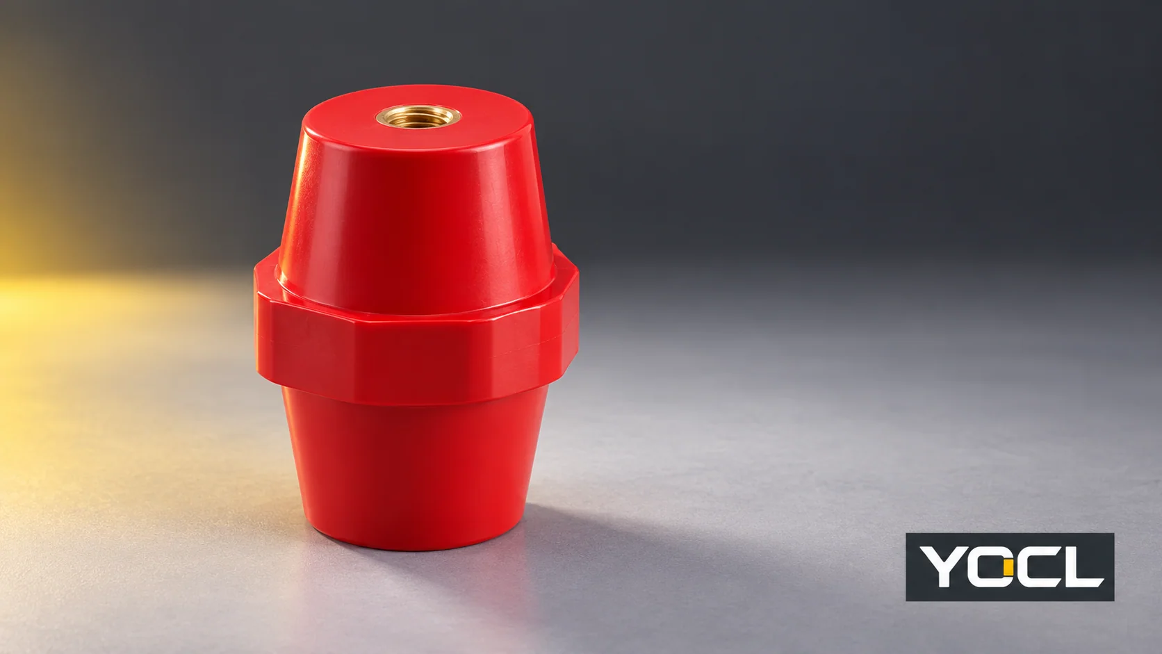
A suspected crack in a busbar support insulator needs a documented assessment before the affected equipment returns to service. The support has both an insulating role and a mechanical role. A surface photograph, a secure-looking bolt or one satisfactory electrical test cannot establish that both functions remain adequate.
Keep the affected equipment out of service while suspected damage is unresolved. Have qualified personnel identify and isolate every relevant energy source, secure against reconnection, address stored energy and verify the work area is dead before inspection. The UK Health and Safety Executive’s HSG85 safe working guidance describes these precautions, including protection from adjacent live parts. Apply the equipment procedure and local requirements. Smoke, arcing or signs of active failure call for the site’s emergency response, not a closer live inspection.
The next decision is whether the observed feature is a confirmed defect or an unidentified surface feature—and what the equipment manufacturer requires for its disposition. There is no universal acceptable crack length, depth or location in this guide.
Record the Condition Before Disturbing It
Once safe access is established, record the equipment identity, support location, part markings, photographs and the relevant drawing revision. Photograph the suspect area with an overall view showing where it sits in the assembly. Record any known fault, transport incident, recent installation work, overheating or environmental exposure. Identify facts separately from assumptions.
Use the busbar insulator overview if the component’s function is unclear. Here the task is to investigate an observed condition and obtain a repair or replacement decision, rather than choose a support for a new design.
An unidentified line could require comparison with a mould feature, scratch or actual material separation. Ask the manufacturer to classify it using the exact part and adequate evidence. Do not assume that a fine line is harmless, but do not label every moulding line a structural crack from a photograph alone. Avoid scraping, flexing, loading or probing the part to make the line more obvious; those actions can alter the evidence or worsen a damaged support.
Link Each Observation to a Safe Next Action
Use this table after isolation and verification. It helps organize the assessment; it does not diagnose a material or approve continued use remotely.
| Observation | Check or evidence to obtain | What the finding means | Next action |
|---|---|---|---|
| A line is visible but its nature is unclear | Clear photographs, exact part identification, location and manufacturer guidance on the observed feature. | Appearance alone has not established whether it is damage. | Keep the condition unresolved until the responsible person obtains a documented classification and disposition. |
| An open split, broken piece or material separation is visible | Record its position and any affected body, insert or mounting interface; assess the surrounding assembly. | There is visible damage whose effect on insulation and support needs assessment. | Keep the equipment out of service and obtain the authorized replacement or repair route. |
| Damage is concentrated around an insert or mounting face | Original hardware and assembly records, part identity, seating condition and relevant installation instructions. | The local interface requires investigation; the appearance does not prove a particular tightening or loading error. | Have the manufacturer or responsible engineer assess the part and mounting arrangement. |
| A support appears displaced, or the busbar or frame has moved | Compare the isolated assembly with the approved layout; record deformation, fixing condition and event history. | The problem may extend beyond one insulator. | Review the supports, busbar, fixings and frame together before deciding the scope of work. |
| Scorching, erosion, deposits or contamination accompany the suspected crack | Preserve the initial condition and record nearby heat, arcing, moisture or chemical-exposure evidence. | More than a surface crack may be involved; the source and extent remain to be determined. | Escalate the assessment and follow approved cleaning, damage-disposition and replacement instructions. |
| Similar damage has occurred before | Previous reports, replaced part numbers, assembly changes, load and fault history. | Replacing the same part alone may leave an underlying problem unresolved. | Require an engineering review of the recurring condition before release. |
In U.S. workplaces within its scope, OSHA 1910.303(b)(7)(iii)–(iv) addresses damage and contamination of internal equipment parts, expressly including insulators, and damage that may affect safe operation or mechanical strength. It supports assessing the equipment condition; it does not provide a universal crack-size acceptance limit for a YOCL support.
Inspect the Support and the Parts It Connects
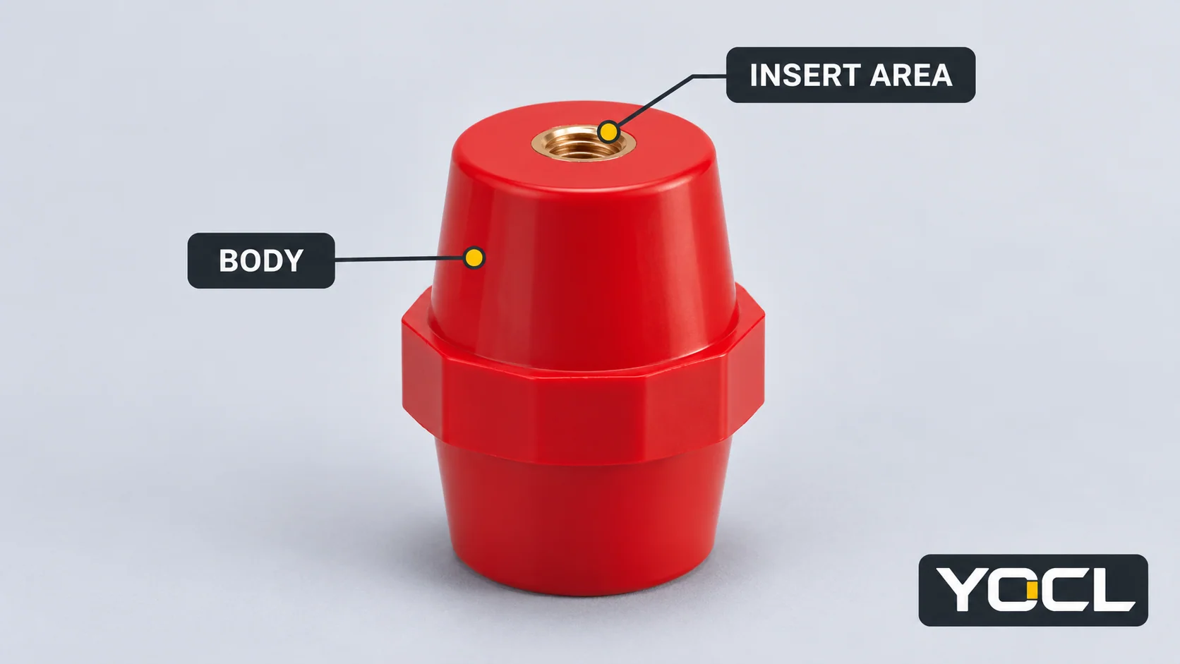
A support inspection needs more than a close-up of the line. Record the visible insulating body, insert area, mounting interfaces and adjacent components as access and the approved procedure permit. Do not force an insert to move or loosen hardware merely to see what happens.
Look for evidence that the support is no longer seated as intended, that the mounting structure is distorted, or that the busbar position differs from the drawing. Record visible damage to adjacent supports and any changed separation or contact with surrounding structures. A qualified assessment should decide whether further access or dismantling is needed and how the busbar will remain safely supported during the work. This article does not supply a removal or load-support procedure.
The result should describe the extent of the affected assembly, not just identify a replacement part. If the visible defect is at one support, inspect the relevant neighboring supports, busbar and fixing arrangement under the equipment instructions. Do not assume every adjacent part is damaged, or that every apparently intact part is proven serviceable.
Investigate the Cause Without Guessing From the Crack Shape
Use the history to direct the next checks. Recent assembly work points toward checking the specified part, hardware, seating and installation records. An impact or transport event calls for review of the affected structure. A known electrical fault calls for the equipment manufacturer’s post-fault assessment. These are investigation paths, not conclusions derived from the crack’s direction.
The Copper Development Association and European Copper Institute’s Copper for Busbars, revised May 2014, explains that high short-circuit currents can produce forces that distort bars and damage supports. Its mounting discussion also connects restraint and deflection with maintained separation. This is association engineering guidance about busbar arrangements, not a fault-withstand rating or damage test for a particular YOCL insulator.
Thermal and environmental records also matter. Document nearby heat damage, moisture, deposits and known chemical exposure so the responsible engineer can compare the actual conditions with the equipment and material requirements. The cause may remain uncertain without further assessment. Do not turn a plausible explanation—such as an assembly error, mechanical movement or an adverse environment—into a confirmed root cause without supporting evidence.
Decide Whether to Replace, Escalate or Hold for Assessment
For confirmed damage, obtain the equipment manufacturer’s disposition and approved replacement requirements. If the manufacturer provides a repair route, it must cover the exact part, defect and application. Glue, filling, sanding, coating or tightening is not a basis for returning a suspect support to service without that authority and the required verification. An improved appearance does not establish restored mechanical or insulating performance.
If the feature remains unidentified, retain the hold and request clarification. A statement that a line is a normal mould feature should identify the part and observed feature sufficiently for the equipment owner to record the decision. A lack of visible progression is not an acceptance criterion unless the relevant approved procedure makes it one.
Replacement also needs more than matching colour, height or screw diameter. Confirm the exact part or an authorized alternative, mounting geometry, thread and engagement requirements, hardware, material, electrical duty, mechanical duty and environmental suitability for the assembly. Use the existing busbar support insulator selection guide for that separate specification task.
YOCL’s SM-series product information identifies a family of moulded supports with metal inserts. Its catalogue fields do not establish the remaining strength of a damaged specimen. In particular, a listed torque-strength value is not automatically an installation tightening torque, and a withstand-test value is not a general operating-voltage approval. Obtain the actual installation and application documents for the selected part.
Verify the Work Before Return to Service
An electrical test answers the question defined by its method, conditions and acceptance criteria. It does not, on its own, establish the mechanical integrity of a cracked support or approve every aspect of a replacement assembly. Likewise, secure hardware alone does not establish the insulation condition. The equipment manufacturer and applicable project procedure determine the inspection and testing required after the authorized work.
Keep a release record containing:
- The original observation, location, photographs and event history.
- The manufacturer’s or responsible engineer’s assessment, including unresolved questions and the authorized scope of work.
- Removed and replacement part identification, approved alternatives and relevant document revisions.
- Findings on the busbar, neighboring supports, mounting structure and hardware, with corrective actions where required.
- Completed inspection and test results, deviations, acceptance criteria and the person authorized to release the equipment.
Before re-energization, qualified personnel should complete the required checks, restore guards and covers, remove temporary work items under the procedure and confirm people are clear. OSHA 1910.333(b)(2)(iv)–(v) addresses verification of de-energization, including possible backfeed or induced voltage, and checks before re-energizing within its U.S. scope. Follow the applicable local and equipment-specific process; if the condition or repair remains unresolved, keep the equipment out of service.
For help identifying a potential replacement from the YOCL busbar support insulator range, provide the existing part information, photographs, mounting drawing, duty requirements and the equipment owner’s disposition. Product identification supports the assessment; the responsible party must approve the actual replacement and return to service.
References
- UK Health and Safety Executive, Electricity at Work: Safe Working Practices (HSG85), safe isolation and verification.
- U.S. Occupational Safety and Health Administration, 29 CFR 1910.303, paragraphs (b)(7)(iii)–(iv), equipment damage and contamination.
- David Chapman and Toby Norris, Copper Development Association / European Copper Institute, Copper for Busbars — Guidance for Design and Installation, revised May 2014, sections 4.3–4.4.
- YOCL ELECTRIC, SM Busbar Support Insulators, product information and exterior image reference.
- U.S. Occupational Safety and Health Administration, 29 CFR 1910.333, paragraphs (b)(2)(iv)–(v), verification and re-energization.