
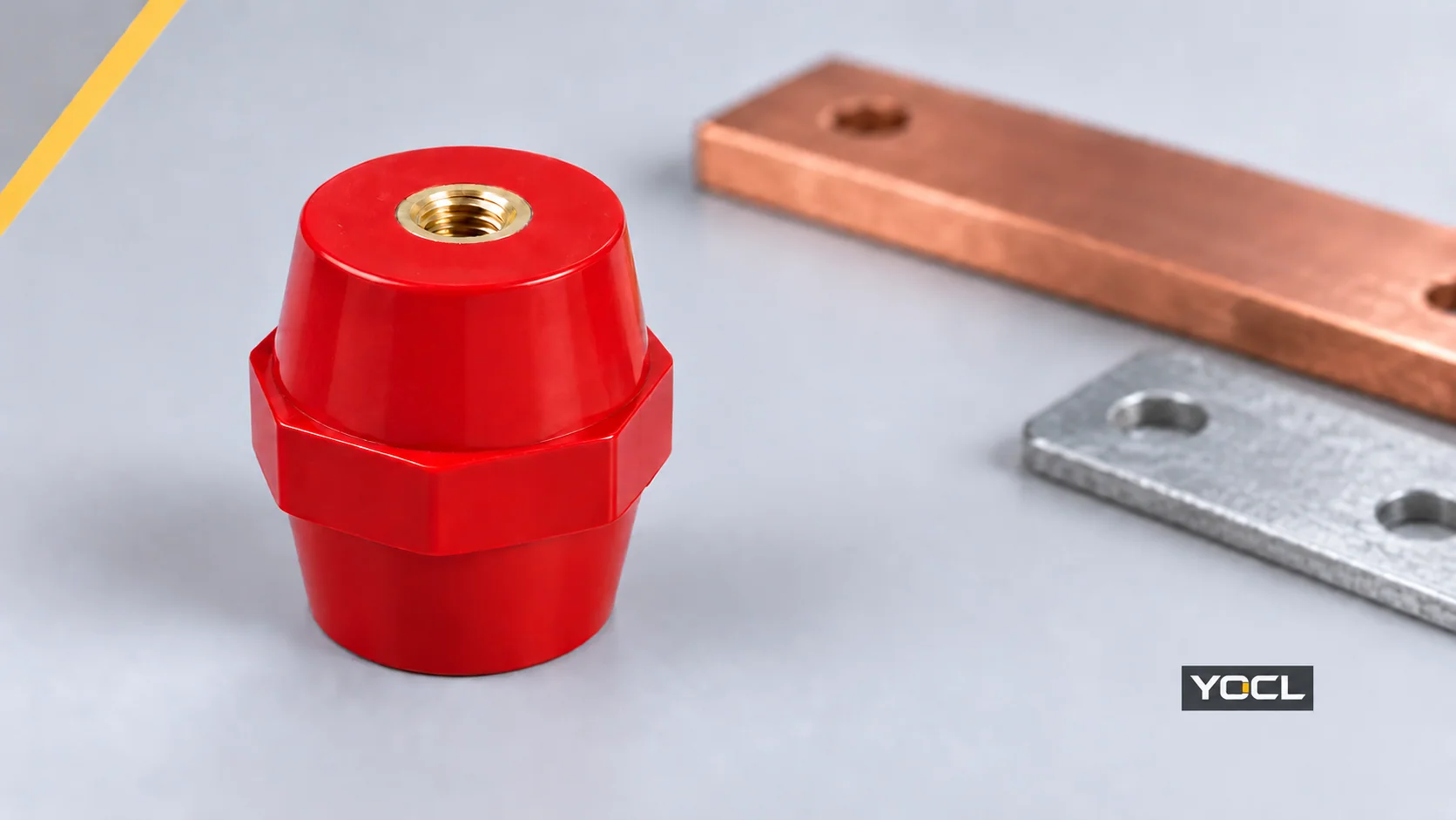
Select a busbar support insulator through four checks: mounting dimensions, mechanical loads, electrical insulation duty, and thermal/environmental conditions. Begin with the proposed busbar arrangement. Use its dimensions to shortlist a model, then establish whether that model and mounting configuration have the evidence needed for the specified duty.
A matching height or thread only starts the selection. The useful output is a candidate record showing what fits, what fails and which requirements remain unresolved. For terminology and rating interpretation, the busbar insulator overview provides the background.
Turn the Layout Into Selection Inputs
Prepare a dimensioned arrangement drawing and a duty sheet before comparing models. Convert each input group into a requirement that can be checked against the supplied part and installation configuration.
| Input to collect | Requirement or selection output |
|---|---|
| Bar material, width × thickness, number of bars and orientation; support positions, spans and adjacent conductors | Defined bar layout and mechanical assessment geometry |
| Mounting height, available envelope, fixing faces, hole centres and threaded interfaces | Exact-model drawing and nominal dimensional shortlist |
| Weight, attached-connection loads, relevant vibration, fault-current information and duration | Load cases and evidence for the proposed support arrangement |
| System/working voltage, AC or DC, insulation and impulse duty, pollution, tracking characteristics and altitude | Required installed insulation distances and supporting electrical data |
| Conductor/support temperatures, humidity, contamination and enclosure conditions | Model-specific thermal and environmental requirements |
Keep the drawing revision with these inputs. If a requirement changes, review the affected selection checks rather than carry forward the previous candidate automatically.
Screen the Complete Mounting Interface
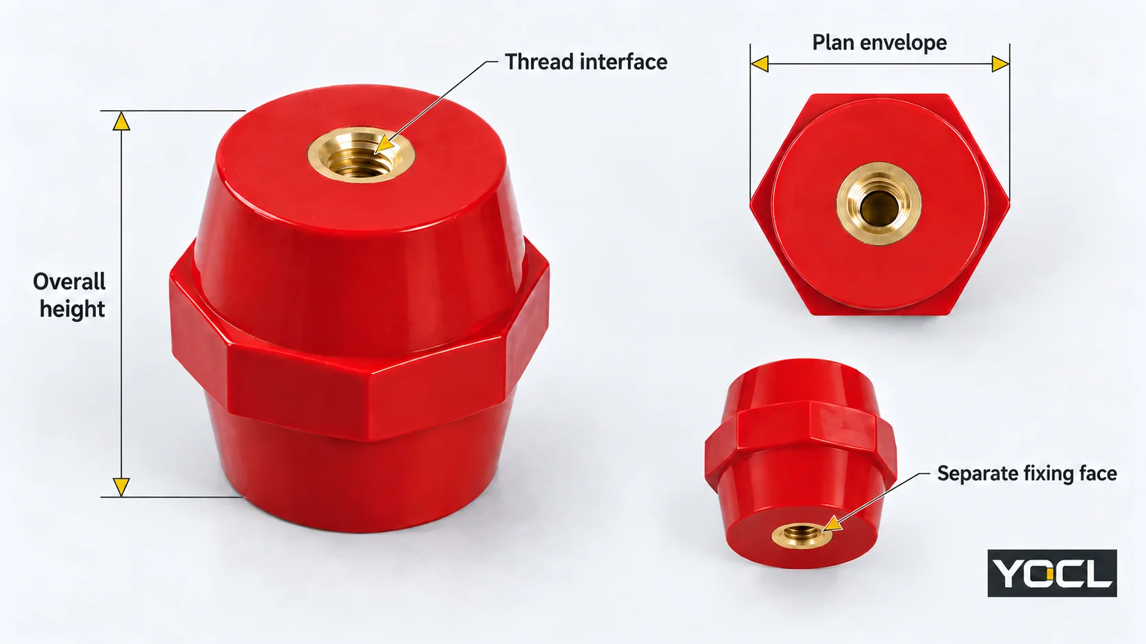
Compare the overall height, all relevant plan dimensions and fixing positions. A diameter, hexagonal across-flats dimension and labelled plan span describe different features. Check the actual drawing direction and the complete envelope.
For threaded supports, specify the thread form, standard, diameter and pitch at each fixing interface. Obtain insert-depth and fastening information for the selected configuration. Published insert depth alone does not specify usable engagement or the bolt length through a bar, washer and mounting stack.
Worked Nominal Screen: Three 40 mm TSM Models
Assume a proposed drawing requires 40 mm nominal support height, no more than 30 mm in the catalogue’s labelled plan direction, and a 6 mm nominal insert-thread diameter. This is a hypothetical geometry screen, with no load or electrical approval implied.
The YOCL TSM catalogue and dimension drawing give these nominal fields:
| Model | Height | Plan span as shown | Nominal thread diameter | Published thread depth | Result for these assumed inputs |
|---|---|---|---|---|---|
| TSM-402 | 40 mm | 30 mm | 6 mm | 13 mm | Retain as a nominal geometry candidate |
| TSM-401 | 40 mm | 40 mm | 8 mm | 13 mm | Reject: plan span and nominal thread differ |
| TSM-40 | 40 mm | 50 mm | 10 mm | 14 mm | Reject: plan span and nominal thread differ |
TSM-402 reaches the next check; it is not yet a confirmed installation match. The catalogue does not state thread pitches or dimensional tolerances. Confirm those details, the full envelope, usable engagement and mounting instructions against the final drawing. The 30 mm label is not a maximum footprint in every direction.
Define Loads for the Installed Arrangement
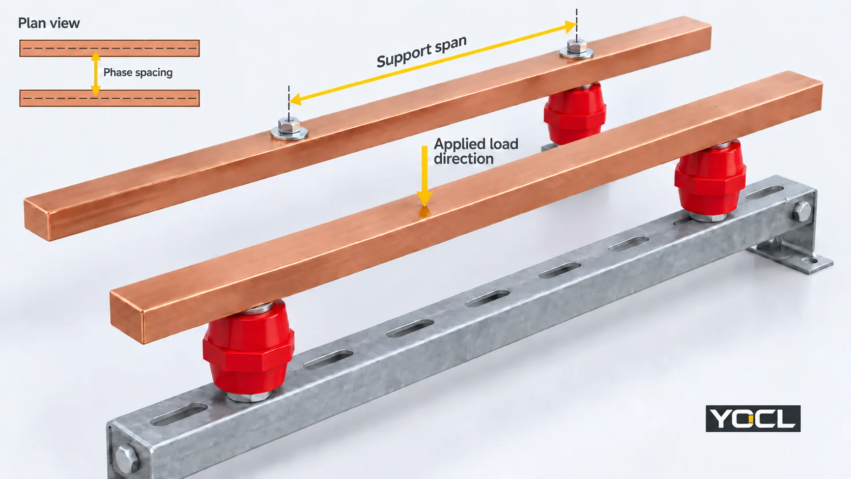
Record each relevant force, its direction and application point, together with the bar section, orientation, span and fixing conditions. Request permissible-load evidence that applies to that case; a catalogue tensile-strength entry does not establish a lateral bending limit or a fault-current rating.
Support span runs along the bar; phase spacing separates adjacent conductors. Bar orientation affects bending under the applied force. Copper for Busbars, sections 4.2–4.4 connects layout, loads, mounting and deflection with maintained conductor separation.
Supply peak fault-current data for electromagnetic assessment and root mean square (RMS) current with duration for heating assessment.
For low-voltage three-phase AC systems at 50/60 Hz, IEC 60909-0:2026 addresses short-circuit current calculation. IEC 60865-1:2011 addresses mechanical and thermal effects within its AC scope. Their public scope statements identify the assessment domains; use applicable engineering documentation for the actual calculation or verified arrangement.
Specify Electrical and Environmental Duty
State working voltage and AC/DC duty, required insulation/impulse performance, pollution and humidity at the insulating surface, material tracking characteristics and altitude. Translate these into required installed clearance and creepage, then check the conductive parts—including bars, fasteners, inserts and frame—on the arrangement drawing. Support height is not either distance.
The SIST-hosted preview of IEC TR 60664-2-1:2011, introduction and sections 1 and 3 explains the input factors and terminology. Use the applicable current equipment requirements for numerical distances. The published scope of IEC 60664-1:2020+AMD1:2025 covers insulation coordination within low-voltage systems and includes altitude considerations; it does not qualify a particular YOCL support.
For thermal and environmental selection, specify conditions at the support, including conductor-contact temperature and enclosure conditions. Identify condensation, contamination and relevant vibration. Obtain the exact compound and finished-part data for those conditions, rather than assign a limit from the material family name. The application-guide preview also identifies heat, vibration and environmental stresses as relevant to insulation performance.
For low-voltage assemblies, IEC 61439-1:2020 establishes general construction, characteristics and verification requirements, used with the relevant part from Part 2 onwards. Component data are inputs to that process. The acceptance evidence must cover the proposed arrangement and its specified duty.
Complete the Candidate Record Before Ordering
Use one record for each proposed model. The worked TSM case produces the following result, with the missing project inputs kept visible:
| Record field | Entry for the worked case |
|---|---|
| Model and source | YOCL TSM-402; published catalogue reviewed; final supply drawing/revision to confirm |
| Nominal geometry result | 40 mm height, 30 mm labelled plan span and 6 mm nominal thread diameter match the assumed screen; 13 mm thread depth declared |
| Remaining mounting evidence | Full envelope, tolerances, thread standard/pitch, usable engagement and fastening instructions pending |
| Mechanical requirement/evidence | Actual bar arrangement, force cases, spans and fault duty not supplied; applicable load/configuration evidence pending |
| Electrical and environmental requirement/evidence | Project insulation distances, working/impulse duty and service conditions not supplied; exact model data pending |
| Disposition | Nominal geometry candidate; duty evidence pending |
For your project, replace the pending entries with actual requirements and document references. Reject candidates that conflict with the required geometry or duty. Retain a candidate for review when evidence is missing; record it as documented for the specified arrangement only when the required checks and applicable assembly verification support that result.
Send this record with the arrangement drawing, revision, quantities and required documents when reviewing the YOCL busbar supports and insulators range. It gives the enquiry a defined model and acceptance requirement.
Related reading: checking insulator threads and mounting drawings.
References
- YOCL — TSM Series Busbar Support Insulators. First-party catalogue and dimension drawing; nominal model data, accessed October 6, 2026.
- Copper Development Association / European Copper Institute — Copper for Busbars, revised May 2014, sections 4.2–4.4. Heating, electromagnetic effects and mounting.
- IEC 60909-0:2026 — Short-Circuit Currents in Three-Phase AC Systems. Public scope: current calculation.
- IEC 60865-1:2011 — Short-Circuit Currents: Calculation of Effects. Public scope: mechanical and thermal effects in AC systems.
- IEC TR 60664-2-1:2011 — Application Guide. SIST-hosted historical preview; visible introduction, input factors and terminology.
- IEC 60664-1:2020+AMD1:2025 — Insulation Coordination. Public scope: low-voltage insulation coordination and altitude.
- IEC 61439-1:2020 — Low-Voltage Switchgear and Controlgear Assemblies: General Rules. Public scope: assembly requirements and verification.