
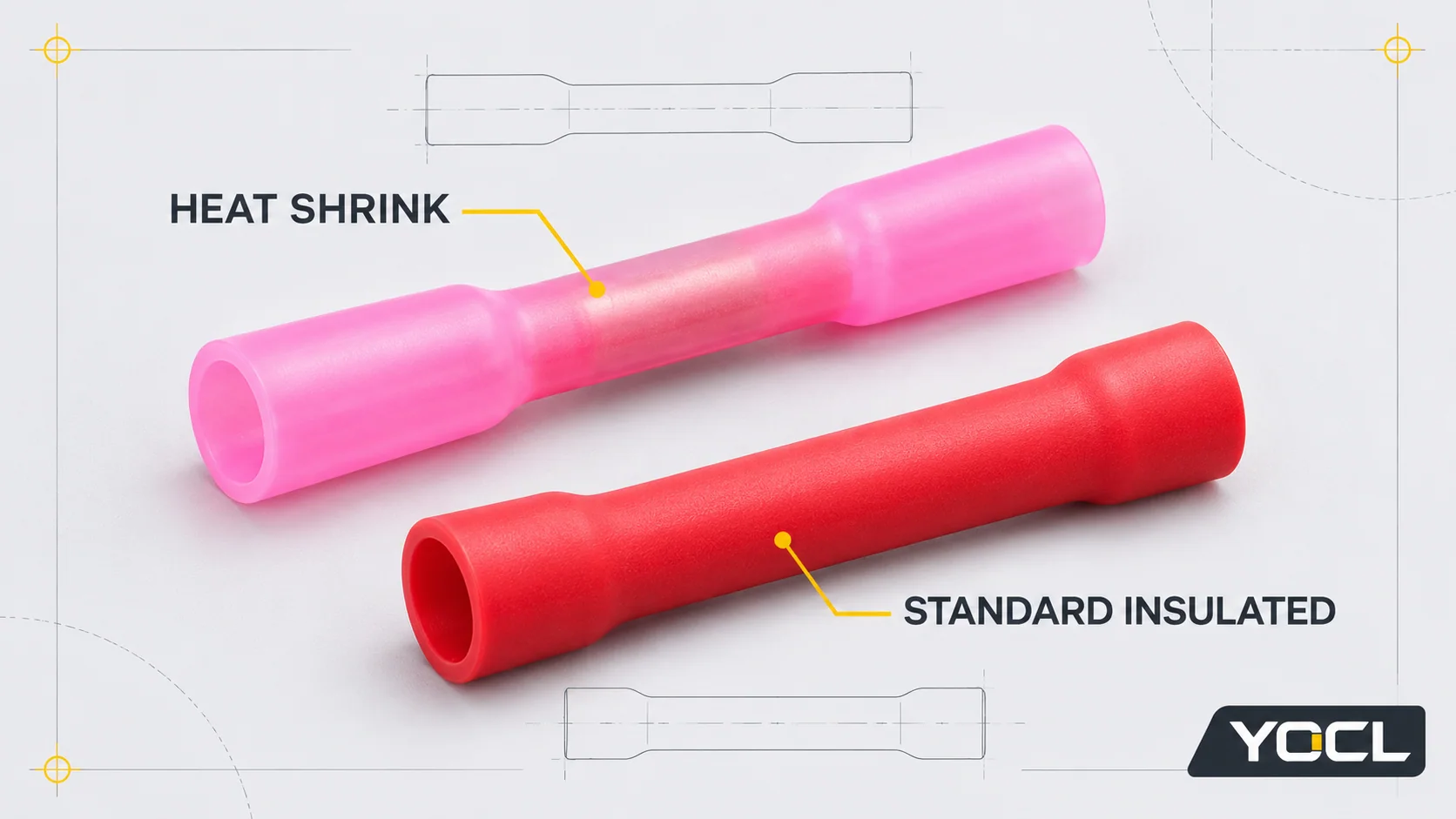
A heat shrink butt connector combines a crimp connection with a sleeve that must be recovered using its specified heating process. A standard insulated splice supplies its ordinary insulation around the connection without making sleeve recovery part of that product’s assembly method. Choose by the exact wire range, crimp/tool compatibility, available assembly space and protection required—not by colour or the expectation that shrinking automatically makes a joint waterproof.
An adhesive-lined heat shrink design is worth assessing when the job requires a sealed insulation interface and its application conditions can be met. An ordinary insulated connector may suit a protected connection whose insulation and electrical requirements it satisfies. Either choice remains unapproved when a required conductor, process or environmental condition is unresolved.
Compare the same inline joint, not just two sleeves
Here, “standard insulated” means an ordinary factory-insulated inline connector, such as YOCL’s PVC-covered BV/PVT examples. It is not a claim of certification to a particular standard. Nylon-covered middle connectors are another construction; their exact model data still govern.
| Decision field | Heat shrink butt connector | Ordinary insulated splice |
|---|---|---|
| Electrical connection | Must use the specified conductor, barrel and crimp tooling | Must use the specified conductor, barrel and crimp tooling |
| Supplied covering | Recoverable sleeve; adhesive lining depends on the exact product | Factory insulation in the declared material and shape |
| Additional assembly process | Specified sleeve recovery, including any adhesive requirements | Follow its crimp/assembly instructions; do not assume its sleeve is heat-recoverable |
| Sealing requirement | Verify the lining, compatible wire-insulation interfaces and finished-assembly evidence | Do not infer sealing merely from the word “insulated”; assess any specified separate protection |
| Space and access | Check the uninstalled connector, heating access and completed envelope | Check connector length, tool access and completed envelope |
| Replacement decision | Same colour or similar prefix does not establish the same wire acceptance | Same rule; an ordinary sleeve is not an interchangeable substitute for a shrink system |
For the broader terminology and terminal shapes, use the crimp terminal overview. This comparison keeps the joining task fixed: an inline splice between conductors.
What the actual YOCL constructions establish
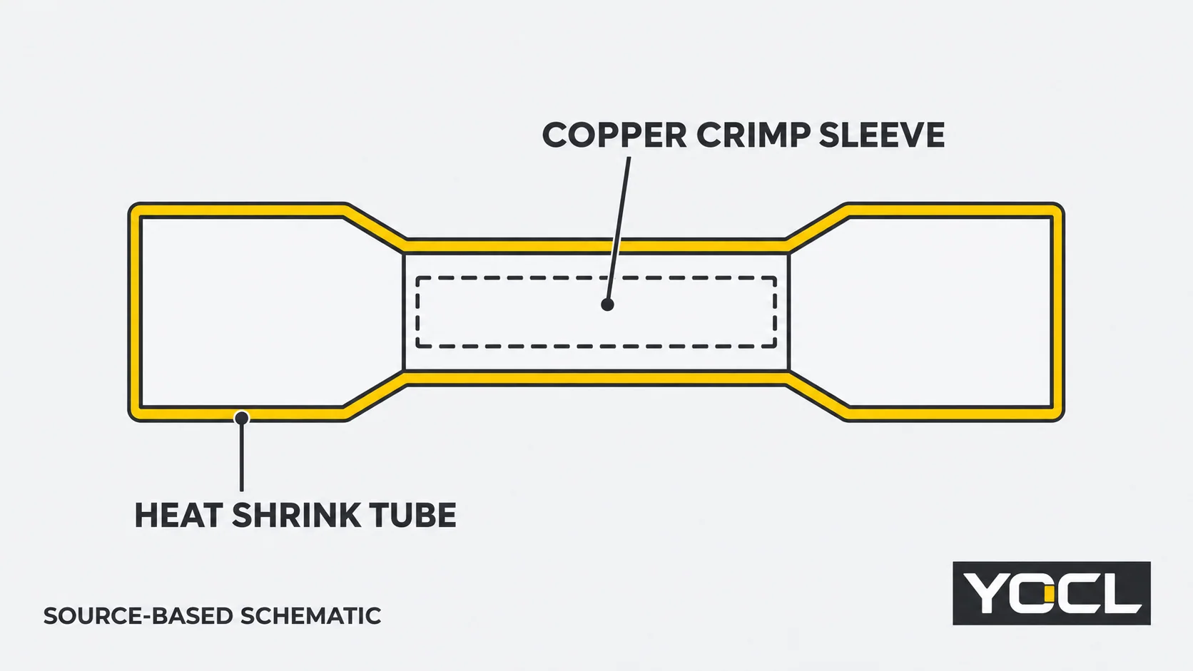
The current BHT product information describes a copper crimp sleeve, PE heat shrink tube and polyamide hot-melt adhesive. Its lining is therefore a documented construction feature, rather than a conclusion drawn from a translucent photograph.
The BV/PVT product information identifies copper with PVC insulation, with BV as the long type and PVT as the short type. The BNY/BNYF range instead identifies copper with nylon insulation. These declarations distinguish constructions; they do not establish a universal ranking for every PVC, nylon or heat shrink connector.
A crimp is still the conductor connection. NASA-STD-8739.4A Change 4, §3.2, describes crimping through deformation of the metal connection around the conductor. That fixed-edition workmanship document has a NASA mission-hardware scope; it is not approval of these YOCL products or a universal industrial installation procedure. NASA original document.
Recovering the sleeve does not replace the crimp. Conversely, a suitable crimp does not by itself establish the sleeve’s required coverage or an environmental seal. Keep those requirements separately identifiable in the chosen assembly instructions.
The same red colour and 1.25 label can hide a wire-range mismatch
The following entries are current YOCL catalogue declarations, checked November 3, 2026. They are a model-identity example, not an approved replacement list.
| Model | Declared conductor range | Catalogue colour | Supplied construction |
|---|---|---|---|
| BHT-1.25 | 0.5–1.0 mm² | Red | Adhesive-lined heat shrink butt connector |
| BV 1.25 | 0.5–1.5 mm² | Red | Long PVC-insulated middle connector |
| PVT 1.25 | 0.5–1.5 mm² | Red | Short PVC-insulated middle connector |
Sources: the BHT and BV/PVT product pages linked above. A model suffix is not a complete conductor specification, and catalogue colour does not override the row’s declared range.
Consider a hypothetical 1.2 mm² conductor. It lies within the listed range for BV 1.25 and PVT 1.25 but above the published maximum for BHT-1.25. The BHT part cannot be accepted as that direct substitution on the available range data, even though both descriptions contain “1.25” and both are red.
The BV/PVT entries pass only this initial range screen. Conductor material and construction, actual barrel acceptance, approved tooling, electrical duty and the rest of the application still need confirmation. Nor does this example recommend moving automatically to the next BHT size: its minimum range and tooling must also match.
Do not add several conductors into one end simply because their areas add to a printed number. The permitted conductor count and combination belong to the exact connector instructions.
Treat sealing as an assembly requirement
BHT’s documented adhesive layer gives it a sealing function to evaluate. It does not, by itself, answer every moisture-exposure question.
Specify the required environment and the two wire-insulation interfaces. The adhesive must be suitable for those surfaces, the sleeve must achieve the specified coverage and recovery, and the completed arrangement must meet the applicable acceptance requirements. A declared shrink ratio describes a recovery characteristic; it is not a finished-joint ingress rating.
For an ordinary insulated splice, identify where any required environmental protection comes from. A PVC sleeve around the metal connector is not proof of a sealed interface at both wire exits. If a separate tubing system is proposed, its selection and installation need their own evidence rather than an assumed upgrade based on appearance.
A wet-location request should therefore state the actual exposure and required assembly evidence. Do not choose a connector merely because its name includes “heat shrink,” and do not treat ordinary insulation as moisture sealing. A recovered sleeve’s appearance alone cannot settle either question.
Check process access and the finished envelope before changing products
An integrated shrink-sleeve connector adds a process requirement. Confirm that the selected assembly instructions can be followed at the intended location, with suitable access and without exceeding the limits of the wires or adjacent equipment. A catalogue recovery temperature is not a complete heat-source setting, nozzle distance or exposure time.
An ordinary insulated connector has its own crimp access and dimensional requirements. Do not heat its PVC or nylon sleeve as if it were a recoverable tube unless that exact product explicitly permits the operation.
Compare the actual drawings as well as the wire range. BHT identifies copper-sleeve dimensions separately from its heat shrink tube dimensions. BV/PVT uses its own insert and overall-length symbols. Similar letters or equal nominal dimensions do not establish identical crimp zones, tool positions or finished space requirements.
The shorter PVT construction is another geometry option, not evidence that the longer BV or BHT is mechanically stronger. Confirm the installed envelope and access to the selected tool. Where the job also requires strain relief or cable support, assess that arrangement separately; do not assign the duty to an insulating sleeve without supporting instructions.
Separate tubing and solder-seal splices are different proposals
A standard insulated connector plus a separately selected sleeve is a multi-component assembly. It may address an application when the complete arrangement is specified and verified, but it is not automatically equivalent to an integrated BHT connector. The tubing must fit over the intended splice and satisfy its own recovery, coverage and material requirements.
The existing heat shrink tubing application guide for a cable splice covers that separate sizing and application task. Its tubing rows and process instructions must not be transferred to BHT merely because both products shrink.
Also distinguish crimp-and-shrink products from solder-seal splices. The crimp-terminal overview identifies these as different joining methods. A sleeve that shrinks is insufficient to identify the electrical connection inside it; specify the actual product and joining process before comparing alternatives.
For the separate PVC/nylon/bare-terminal material question, use the terminal-insulation comparison. Material-family names do not replace model-specific limits.
Choose heat shrink, standard insulation, either or neither
| Application condition | Bounded decision |
|---|---|
| Protected joint, no environmental seal required | An ordinary insulated splice may remain eligible if its electrical, conductor, tooling and insulation requirements match |
| An integral adhesive-lined sleeve is required | Assess the exact heat shrink connector and its compatible surfaces, process and assembly evidence |
| Heating cannot be performed under an approved process | Hold the shrink proposal; an ordinary connector remains an option only if it satisfies all required protection without that process |
| Both constructions satisfy the complete duty | Either can remain eligible; compare actual assembly work, space and maintenance requirements |
| Sealing, conductor fit or tooling is unverified | Neither is approved yet; identify the missing requirement instead of substituting by colour |
Turn the decision into a model-by-model record. Include the conductor material, section and strand construction on each side; required electrical duty; wire-insulation details; connector and tool references; available space; proposed heating process where applicable; and the required insulation or environmental acceptance evidence.
For a YOCL comparison request, send that record with the exact proposed models and quantities. Identify whether you are keeping an existing assembly, proposing a direct replacement or changing its protection system. Those are different approval questions even when the two loose connectors look similar.
References
- YOCL product information, BHT Heat Shrinkable Butt Connectors — declared materials, BHT-1.25 conductor range and original product/diagram references; checked November 3, 2026.
- YOCL product information, BV/PVT Full-Insulating Middle Connectors — PVC/copper construction, long/short variants and model-specific wire ranges; checked November 3, 2026.
- YOCL product information, BNY/BNYF Nylon Middle Connectors — nylon/copper construction; checked November 3, 2026.
- NASA, NASA-STD-8739.4A Change 4, April 13, 2022 — §3.2 crimping terminology, within the document’s mission-hardware scope.