
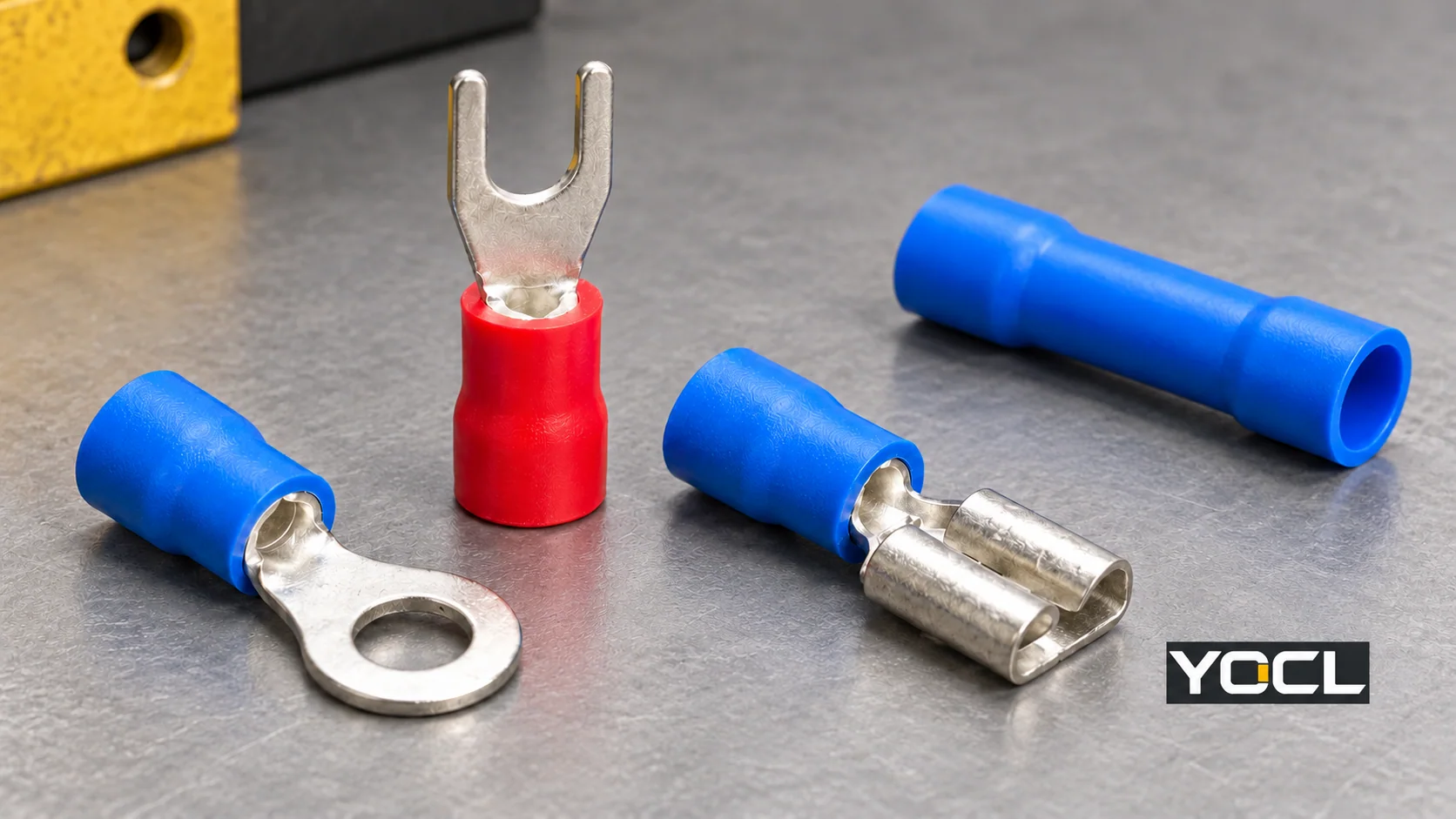
A crimp terminal is a conductive fitting attached to a wire by compressing its crimp region around the conductor. Its contact end provides a particular connection, such as a ring, fork, pin or receptacle. Related crimp splices use compression to join conductors to each other. NASA’s crimping terminology, §3.2, describes the resulting electrical and mechanical connection.
To identify the part, separate contact shape, crimp construction and insulation. “Nylon-insulated ring terminal” combines a covering description with a connection style. Neither description tells you the complete wire range, mating dimensions or assembly requirements.
The Wire Connection and the Contact End Have Different Jobs
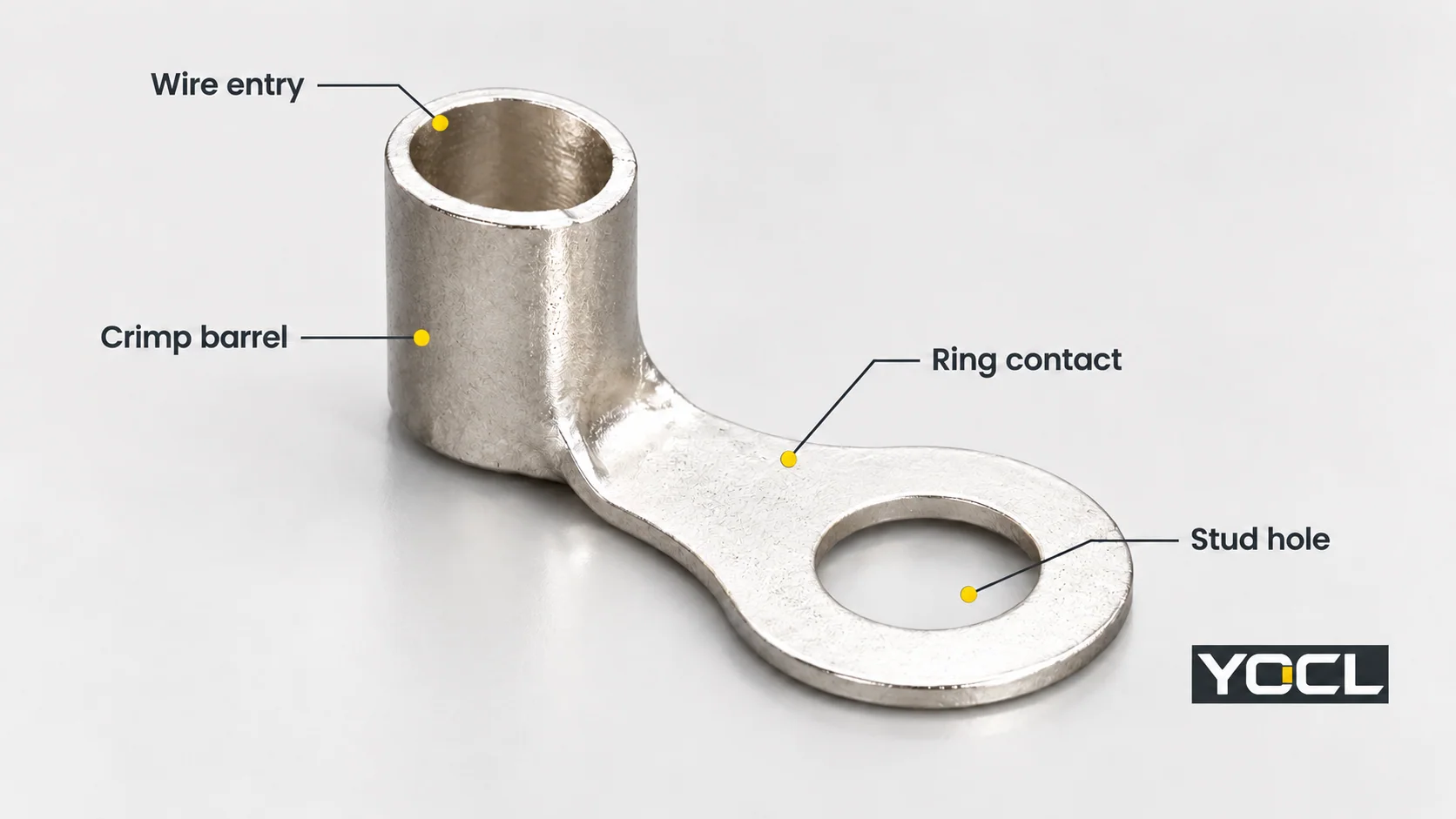
On a ring terminal, the barrel receives the conductor and forms the crimped wire connection. The ring contact presents a closed hole and contact face to a compatible bolted connection. YOCL’s RNB non-insulated ring terminal makes these exterior features visible.
The same part can carry several descriptions:
| Description | Question it answers | Example |
|---|---|---|
| Contact or joining style | What does the terminal meet or join? | Ring for a stud connection; receptacle for a mating tab; butt splice for an inline joint |
| Crimp construction | What conductor-side construction is specified? | Single- or double-crimp version of a named series |
| Insulation construction | What covering is supplied? | Bare metal, PVC sleeve, nylon sleeve or heat-shrink sleeve |
Single crimp and double crimp are construction labels, not conductor counts. In YOCL’s PTV/PTD pin-terminal information, PTV identifies the single-crimp version and PTD the double-crimp version. The label does not authorize two wires or supply a universal insulation-support or tooling specification.
The terminal, conductor and tooling form a specified combination. NASA’s §12.3.3 explicitly follows manufacturer recommendations for contact–conductor combinations within its mission-hardware scope. This supports checking the actual combination; it does not make NASA’s aerospace tooling or testing rules universal instructions for these products.
Identify the Connection Style Before Comparing Sleeves
Use the contact or joining form to find the relevant drawing. These examples identify families, rather than approved substitutions.
| Form | Connection presented | What the next document must resolve | YOCL example |
|---|---|---|---|
| Ring | Closed eye for a compatible bolt or stud | Hole diameter, contact footprint and fastening arrangement | RV ring terminal |
| Fork / open spade | Open-ended tongue for a compatible screw connection | Fork opening, tongue width and receiving clamp arrangement | SV fork terminal |
| Flat blade | Projecting flat insertion contact | Blade width, thickness, usable length and accepted entry | DBV blade terminal |
| Pin | Narrow projecting insertion contact | Actual pin profile, dimensions and receiving-terminal acceptance | PTV/PTD series above |
| Flat-tab quick disconnect | Female receptacle engages a specified mating tab | Both tab width and thickness, mating form and insulation coverage | FDD/FDVD female terminal |
| Bullet | Male bullet engages a corresponding female contact | Bullet dimensions and the exact mating counterpart | MPD/MPVD male bullet |
| Inline butt splice | Joins conductors end to end, rather than presenting a stud contact | Allowed wire arrangement, conductor ranges and splice construction | BV/PVT middle connector |
“Spade” needs a drawing beside it. Identify the actual contact: an open stud tongue and a tab/receptacle pair perform different mating jobs. Likewise, a DBV blade is not automatically the mating tab for an FDD receptacle simply because both involve flat metal.
One Ring Style Can Have Different Insulation Constructions
Changing the sleeve does not change a ring into a fork. These actual YOCL families keep the ring-style connection while supplying different coverings:
| Construction | Catalogue example | What the covering description leaves open |
|---|---|---|
| Non-insulated | RNB, shown above | The finished assembly’s insulation, clearance and protection arrangements |
| PVC-insulated | RV 1.25 group; PVC is expressly declared for this group | Exact wire acceptance, dimensions and installed protection |
| Nylon-insulated | RNY/RNYD ring terminals | Exact model data and single- or double-crimp construction |
| Heat-shrink covered | RHB ring terminals | The selected product’s crimping, sleeve recovery and any declared sealing information |
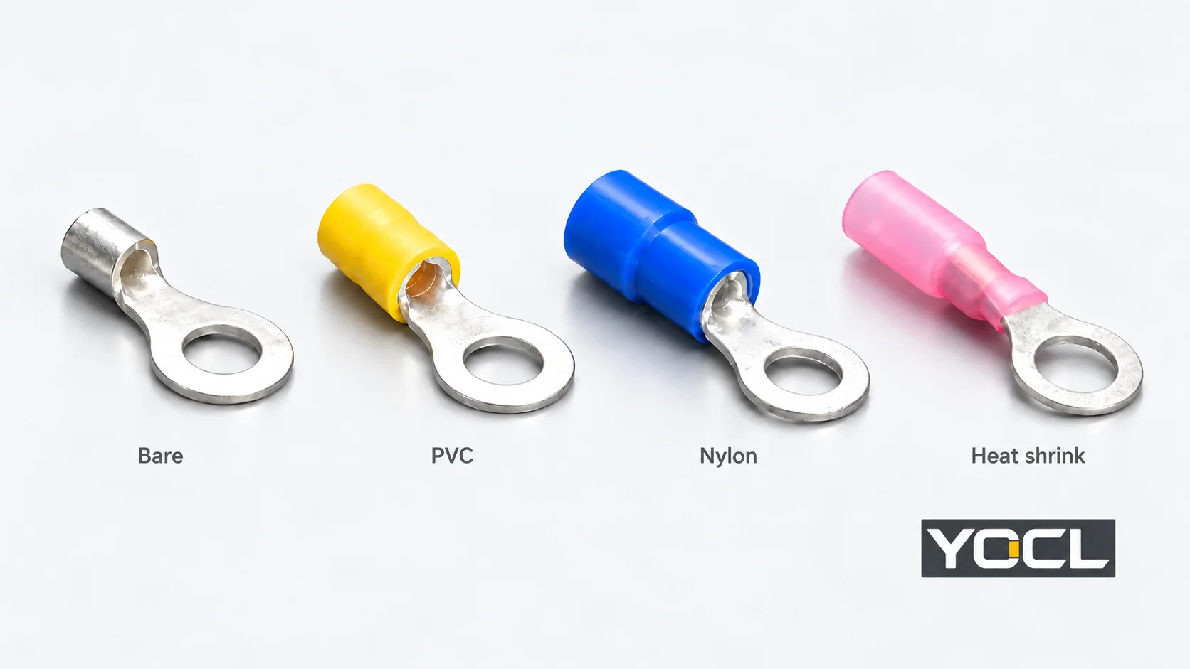
A factory sleeve may cover the wire barrel while leaving the contact end exposed, as these ring examples show. “Insulated” therefore does not establish complete touch protection for the assembled connection. Nor does “nylon” establish a universal temperature advantage over PVC. Read the exact model’s material and operating data.
Heat-shrink appearance also does not identify the joining method. YOCL’s heat-shrink terminal and splice range distinguishes crimp products from HXT solder-seal splices. A solder-seal joint uses its specified soldering/heating method; it is not a crimp merely because its sleeve shrinks. A heat-shrink sleeve alone is also insufficient evidence of a waterproof joint.
Wire Range and Stud Hole Are Separate Specifications
Two rows in the RV catalogue illustrate why a colour or short model description is incomplete:
| YOCL model | Declared conductor range | Catalogue colour | Ring-hole d2 |
|---|---|---|---|
| RV 1.25-3 | 0.5–1.5 mm² | Red | 3.2 mm |
| RV 1.25-4S | 0.5–1.5 mm² | Red | 4.3 mm |
Both belong to the PVC-declared RV 1.25 group, yet their hole diameters differ. The prefix 1.25 does not mean only a 1.25 mm² conductor, and red does not specify the stud interface. These are manufacturer catalogue declarations, not an approval to substitute one model for the other.
Conductor cross-section in mm² is an area; hole or contact dimensions in mm are lengths. Neither is the insulated wire’s outside diameter. For a disconnect, the equivalent receiving-side question concerns the mating tab’s width and thickness. Keep these fields separate when reading a drawing.
Follow the Part’s Job to the Next Resource
Nearby terms overlap, but they do not all name the same component:
| Your remaining question | Where to continue |
|---|---|
| Is this a sleeve preparing stranded wire for a clamp? | What Is a Wire Ferrule? — conductor-end preparation and terminal compatibility |
| Is this a cable-to-equipment lug? | What Is a Cable Lug? — barrel and equipment interfaces; some lugs use compression, others mechanical clamping |
| Does the component join wires, and which points connect? | What Is a Wire Connector? — joining mechanisms and circuit arrangements |
| Is this the supported device receiving the wire end? | What Is a Terminal Block? — clamping assemblies and accessories |
| Which terminal shape and covering should I investigate? | YOCL wire terminals and ferrules — routes to PVC, nylon, bare and heat-shrink families |
Once the family is identified, use the full model drawing and the applicable terminal, conductor, tool and receiving-equipment instructions. That is where wire acceptance, mating fit and assembly requirements become specific.
Related reading: PVC, nylon and non-insulated terminal options.
References
- NASA — NASA-STD-8739.4A, Change 4: Workmanship Standard for Crimping, Interconnecting Cables, Harnesses, and Wiring, Change 4 dated April 13, 2022; §§3.2 and 12.3.3, within the document’s mission-hardware scope.
- YOCL product information — RNB Non-Insulated Ring Terminals; exterior barrel/ring form and bare construction.
- YOCL product information — PTV/PTD Pin Terminals; contact profile and crimp-construction labels.
- YOCL product information — RV Pre-Insulated Ring Terminal; group-specific PVC declaration and model dimensions.
- YOCL product information — SV Pre-Insulating Fork Terminal; open fork and dimensional fields.
- YOCL product information — DBV Pre-Insulating Blade Terminal; flat contact form.
- YOCL product information — FDD/FDVD Female Terminals; receptacle, tab dimensions and covering.
- YOCL product information — MPD/MPVD Bullet Male Terminal; male bullet form.
- YOCL product information — BV/PVT Middle Connectors; inline joining form.
- YOCL product information — RNY/RNYD Nylon Ring Terminals; nylon covering and construction variants.
- YOCL product information — RHB Heat Shrinkable Ring Terminals; heat-shrink covering.
- YOCL — Heat Shrink Terminals & Splices; separate crimp and solder-seal families.