
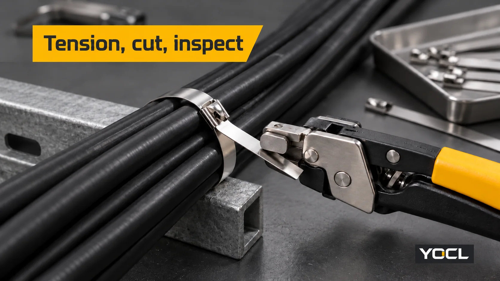
Use an installation tool matched to the stainless steel tie’s locking head, band width, thickness and finish. Route the band correctly, tension it using the approved tie/tool setting, and remove the surplus tail with the specified cut-off method. Inspect the fastening after releasing the tool: the lock must retain the band, the cable jacket must remain undamaged, and the cut end must not leave an exposed injury or abrasion hazard.
There is no universal tension setting or tail-folding method for every stainless steel cable tie. The procedure below covers bundling and securement with factory-made ties. It assumes the cable route and support arrangement have already been selected; it does not qualify a tie as primary cable support or replace the operating instructions for a particular installation tool.
Match the Tool to the Band and Locking Head
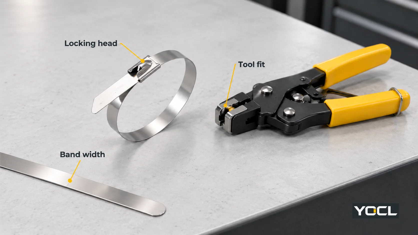
A tool that can pull a metal strap is not necessarily suitable for installing that tie. Before starting, match these details:
- Band width and thickness: both must fall within the tool’s documented capacity.
- Lock and tail geometry: the gripper or hook must engage the intended part of the tail, and the tool must seat as its instructions require.
- Finish: confirm suitability for the actual uncoated or coated band, including its finished dimensions.
- Cut-off method: establish whether the tool cuts automatically at its setting or uses a separate manual cutting action. Do not infer this from the tool’s appearance.
The YOCL BZ ball-lock catalogue lists different recommended tools by width:
| BZ-family band width | Catalogue-recommended tools |
|---|---|
| 4.6, 7.9 or 10 mm | CT02; HT-338 |
| 12 or 12.7 mm | CT02 |
| 16 or 19 mm | LQB; C002 |
These are YOCL catalogue recommendations, not a tool operating manual or a complete qualification of every thickness and coating combination. Confirm the supplied configuration and obtain its installation instructions before choosing the setting or cutting sequence. Do not transfer this BZ table to a different series solely because the band width matches.
For example, the catalogue lists CT02 and HT-338 for a 7.9 mm BZ-family band. It does not establish a shared dial setting for those tools. A tool name, tie width and tensile-strength figure are three different specification fields.
If the tool cannot seat without twisting the band or pressing against a cable, change the access or pairing before proceeding. For recognition of the different constructions, use the stainless steel cable tie overview.
Prepare the Bundle and Work Area
Arrange the cables in their intended route before fastening them. Do not use the tie to pull a misrouted cable into position or transfer the bundle’s weight away from its intended supports. Leave access to the locking head and the tool’s operating path.
On installed electrical equipment, follow the site’s isolation and verification procedure before introducing conductive ties or cutting tools. For US workplaces, OSHA 1910.333 addresses deenergization, lockout/tagout and verification when working on or near exposed electrical parts. This guide does not describe energized work.
Assess the hazards from the band edges and cut-off tail. Use task-appropriate hand protection and eye protection where cutting can eject material. In US workplaces, OSHA 1910.138 requires hand protection selected for the task and hazards; OSHA 1910.133 covers eye protection against flying particles. Keep hands clear of the cutting and gripping mechanisms.
Check the tie, gripper and blade before use. Reject a tie with a damaged head, kinked band or unacceptable coating damage. Remove a tool from use if its gripping or cutting parts are damaged. Provide a way to collect the offcuts so they cannot fall into electrical equipment.
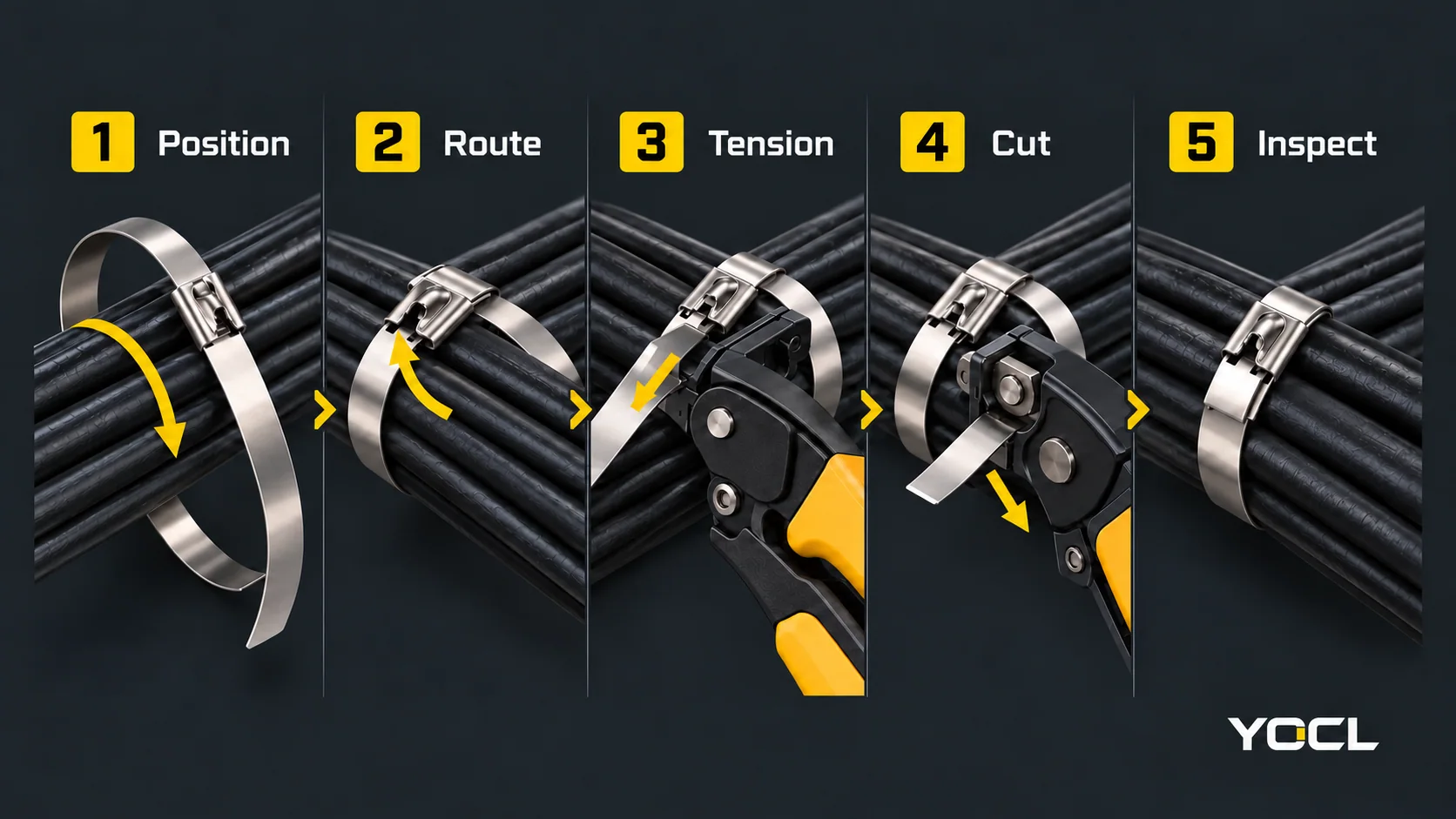
Install, Tension and Cut in Five Steps
1. Position the Band Without Trapping or Twisting a Cable
Place the tie at the specified fastening point. Keep the band flat against its intended contact surfaces, with the head accessible for installation and later inspection. Check around the bundle, including the side hidden from the operator.
Expected result: the cables remain in their intended arrangement, and the band has no twist, trapped loose wire or misplaced contact edge.
Stop if the tie crosses a connector, pulls on a termination or bears on a surface that the assembly specification does not permit. Correct the route or fastening location first.
2. Complete the Routing Required by That Lock
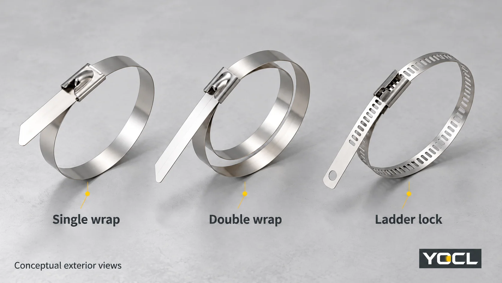
For a single-wrap ball-lock tie, pass the tail through the locking head in the direction shown by its instructions and take up the initial slack. Leave enough free tail for the installation tool to engage. Hand snugging prepares the band for the tool; it does not establish the final installation tension.
Check these YOCL series differences before applying the same sequence to another tie:
- BZQ double-wrap ties: the band passes through the buckle twice before final tightening. Select a length that accommodates both passes; do not treat it as a single-wrap tie.
- JT ladder ties: the ladder band uses multiple-hook locking and an enlarged tail slot for a hook-type installation tool. Its documented construction avoids additional rolling or folding of the band.
- BZW spring ties: the wavy section provides compliance around the bundle. Follow that series’ routing and tension requirements; a flat-looking finished band is not an acceptance target for the spring section.
Expected result: the correct number of passes and engagement features are present, with the head and tail aligned for the specified tool.
If the tail will not feed or the lock does not engage as described, stop. Do not force the head open or modify the band to make it fit.
3. Apply the Documented Installation Tension
Engage the tool at its specified position on the tail and head. Use the approved setting and operating sequence for that tie/tool combination. Keep the tool aligned as directed while taking up the remaining slack; do not use it as a lever against the bundle.
Loop tensile strength is not installation tension. The UL Solutions cable-tie application guide, updated July 2026, describes loop tensile strength as a characteristic of the engaged strap and locking mechanism under test. That test value does not specify the force a tool should apply during installation. Do not use it, or an assumed percentage of it, as a tension setting.
The required result is the securement defined by the assembly specification without cutting, flattening or otherwise damaging the cable jacket. A visual check can reveal damage or obvious looseness, but cannot prove that the correct force was applied. Where the process requires force verification, use the specified measurement method.
For repeated assembly work, check the first completed installation using the approved process before repeating the setting across the batch. Record the tie configuration and tool setting. If the manufacturer has not supplied a suitable setting or method, resolve that pairing before production rather than increasing force until the bundle looks tight.
Stop if the gripper slips, the head twists, the band kinks or the jacket begins to deform. Additional pulling is not a reliable repair for an unsuitable pairing or damaged part.
4. Remove the Tail With the Specified Cut-Off Method
For a tool with automatic cut-off, complete its normal cycle as instructed. For a tool with a separate manual cut-off action, maintain the required tool position and use the stated sequence. Those operating details belong to the actual tool manual; they are not interchangeable between tools.
Keep the offcut directed away from people and contain it without placing a hand in the cutting path. If separate cutting is permitted, use a cutter rated for the stainless band and its dimensions. The cutting action must not trap or nick a cable beneath the tail. Do not assume that cutters intended for nylon ties are suitable for steel.
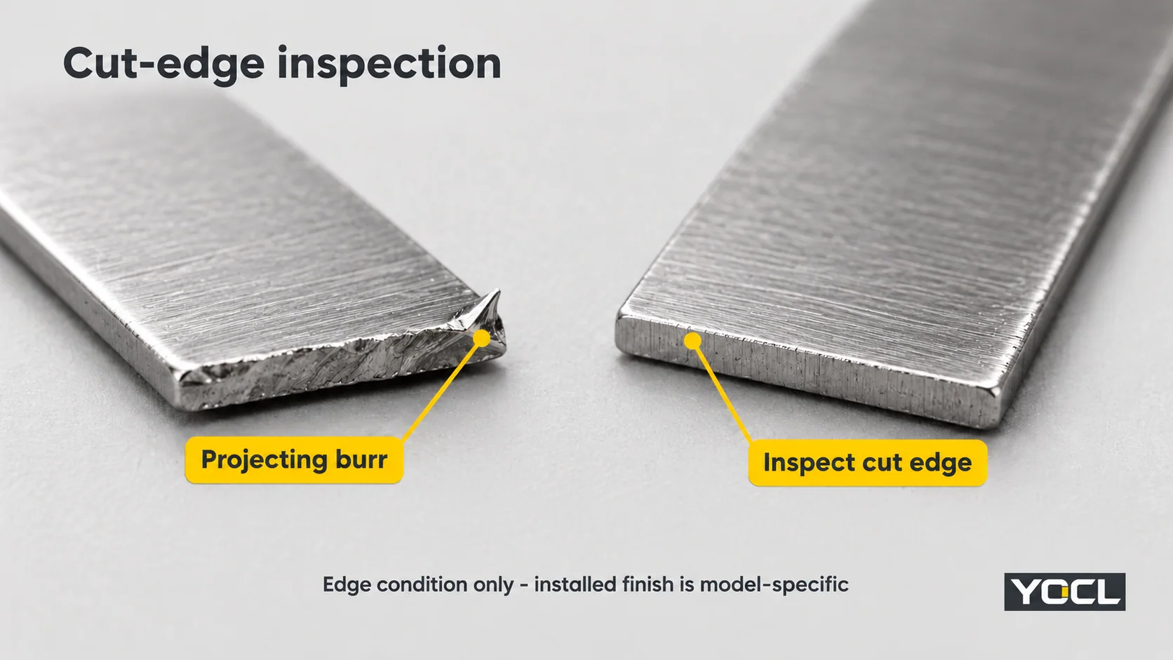
A short tail can still have a sharp edge. Inspect the actual cut rather than accepting it because the tool is described as a flush cutter. Use the specified finished-tail geometry, whether that is a flush cut, a guarded end or another documented arrangement.
Do not automatically fold the remaining tail back over the head. Fold-back, crimping and rolling are appropriate only where the tie/tool instructions specify them. An improvised fold can leave an exposed corner or interfere with the lock. Grinding or filing beside installed cables also introduces debris and jacket-damage risks; it is not a default finishing step.
5. Inspect the Fastening After Releasing the Tool
Inspect the installed tie with the tool removed. A band held tight by the tool has not yet demonstrated that its lock will retain the completed fastening.
Use the following practical checklist alongside the product and assembly requirements. It is not an IEC/UL test or a substitute for specified load or force measurements.
| Check | Accept when | Stop or rework when |
|---|---|---|
| Lock and routing | The head remains correctly engaged and the specified routing is complete | The band backs out, a hook is not engaged or a required pass is missing |
| Bundle and jacket | The intended route is maintained, with no visible cut or damaging deformation | The jacket is nicked, crushed or displaced at a band edge |
| Coated surfaces | Contact surfaces remain in the condition required for that configuration | Damage exposes a surface that the specification requires to remain protected |
| Cut end | The specified finish is achieved without an accessible sharp projection or cable-contact hazard | A burr, projecting corner or incorrectly positioned tail remains |
| Work area | Offcuts are collected, tools removed and access restored | Loose conductive pieces or a tool remain in or around the equipment |
Use lighting and, where necessary, magnification to inspect the edge. Do not slide an unprotected finger along the cut end to test whether it is sharp.
A neat-looking tie does not establish a primary-support rating. UL’s guide distinguishes securement from supporting cable weight. Keep the completed fastening within the product’s documented use and the installation’s support design.
When the Installation Does Not Pass
| Observation | Check before continuing | Appropriate next action |
|---|---|---|
| Band slips while the tool pulls | Tail engagement, gripper condition and the documented band/tool match | Correct the setup or service the tool; replace a damaged tie rather than gripping harder |
| Loop becomes loose after tool removal | Lock engagement, routing and whether the chosen construction suits the bundle | Hold the work for review; replace the tie or change the specified arrangement rather than repeatedly over-tensioning it |
| Tail is burred or projects into a handling area | Blade condition, tool seating and the specified finished-tail geometry | Correct the cutting process; rework only by an allowed method, otherwise replace the tie |
| Jacket or coating is damaged | Contact point, tool path and tension method | Assess the affected cable or coating and replace unacceptable parts before reinstalling |
When removing a failed tie, protect the bundle and use the removal method appropriate to that construction. Do not assume a self-locking tie has a release feature or can be reused after cutting. Reinspect the cable before fitting a replacement.
Record the Tie, Tool and Inspection Result
For repeatable installation work, record: tie series and size; coating; tool model; setting or procedure reference; completed-routing check; jacket/coating condition; cut-end result; and operator/date. Add any measured acceptance result required by the assembly specification. This distinguishes a documented installation from one that only appears tight.
For a YOCL installation specification, send the series, band dimensions, finish, actual bundle and proposed tool through the stainless steel cable tie product page. Request the matching installation instructions and acceptance criteria before fixing the production method.
Related reading: comparing stainless tie material grades.
References
- YOCL – BZ Ball-Lock Stainless Steel Cable Ties. First-party catalogue; width-specific recommended tooling, accessed October 23, 2026.
- OSHA – 29 CFR 1910.333: Selection and Use of Work Practices. US electrical-work safety requirements.
- OSHA – 29 CFR 1910.138: Hand Protection. US workplace hand-protection selection.
- OSHA – 29 CFR 1910.133: Eye and Face Protection. US workplace flying-particle hazards.
- YOCL – BZQ Double-Wrap Ball-Lock Stainless Steel Cable Ties. First-party product information; two-pass routing.
- YOCL – JT Ladder Self-Locking Stainless Steel Cable Ties. First-party product information; multiple-hook lock and tool engagement.
- YOCL – BZW Spring Ball-Lock Stainless Steel Cable Ties. First-party product information; compliant spring section.
- UL Solutions – Positioning Devices: Cable Ties for Cable Management of Electrical Installations, Application Guide, updated July 2026. Pages 3-4; loop tensile strength and securement/support distinctions.