
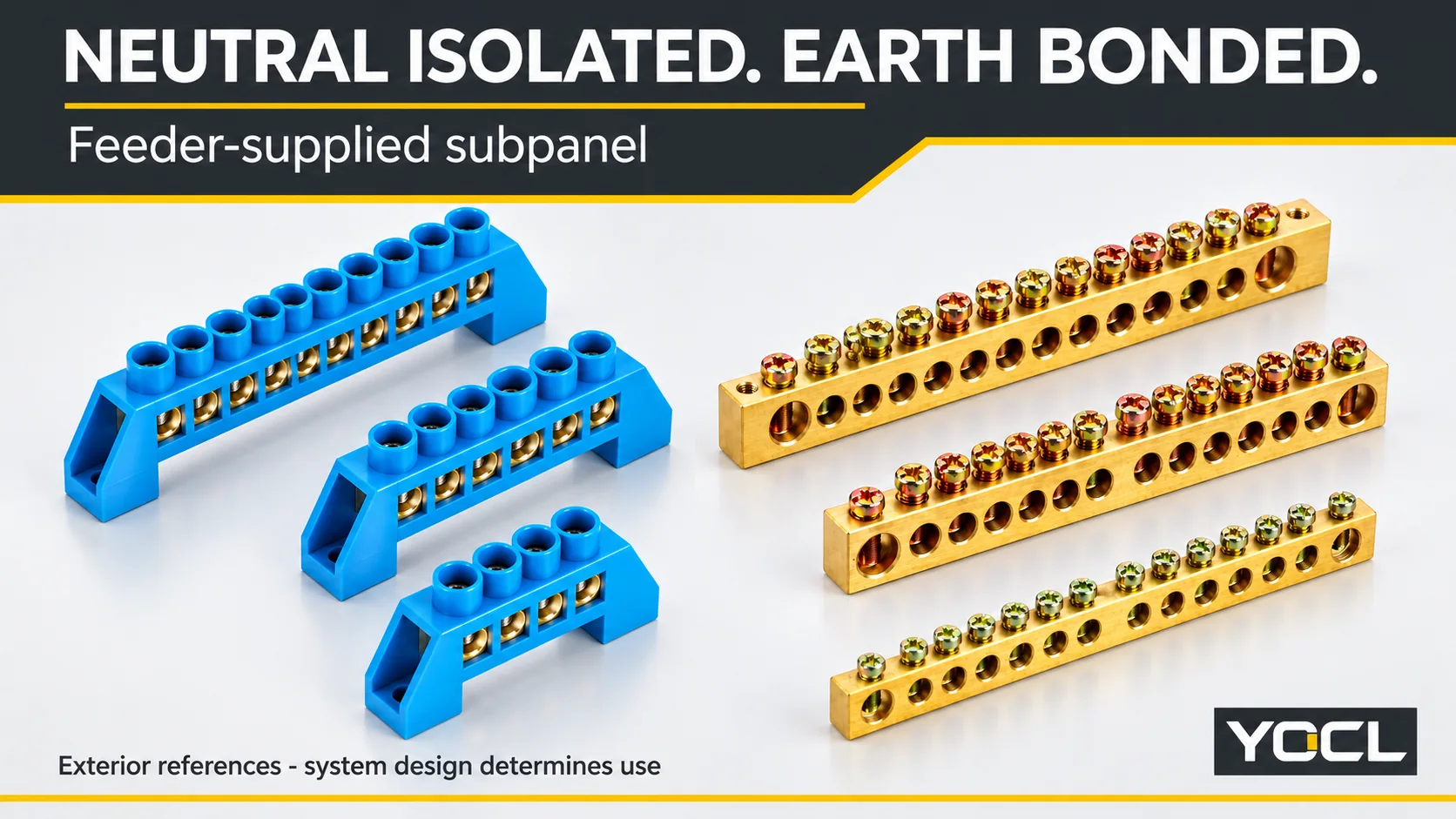
In the ordinary NEC service-and-feeder arrangement, neutral bonds to equipment ground at the service disconnect; it stays isolated in a downstream subpanel. “Main panel” means that service location here, not any cabinet with a large breaker.
| Location | Neutral bar | Equipment-ground bar | Neutral-to-case bonding screw or strap |
|---|---|---|---|
| Service disconnect | Intentionally bonded through the main bonding jumper | Bonded to the enclosure and service neutral | Manufacturer’s identified bonding provision used |
| Feeder-supplied subpanel | Insulated from the enclosure and equipment ground | Bonded to the enclosure | No connection joining neutral back to the case |
Bond at the service point, not again in the feeder panel. This is an identification guide for qualified assessment, not instructions to open or modify a panel.
NEC: two bars that look identical
A row of brass screw terminals does not identify its electrical function. In a correctly configured feeder subpanel, the neutral assembly is insulated from the metal enclosure. Equipment grounding conductors terminate on the separate grounding assembly, which has a documented conducting connection to the enclosure.
White or gray insulated conductors are familiar US neutral identifiers; bare or green equipment-grounding conductors belong to the protective path. These are recognition cues, not permission to trust an unknown installation. Conductors may already be mislanded, and a hidden strap or fastener can defeat an apparently insulated neutral support.
The YOCL YC038 brass neutral and earth-bar page illustrates why exterior shape cannot settle the question: the same common-conductor form can serve the role assigned by the approved assembly. The BS001-0609 neutral-bar page provides a different supported exterior form. Neither product name establishes an approved US panel installation.
Identify the assembly from its diagram and markings, its mounting and bonding arrangement, and the conductors assigned to it. “Floating neutral bar” means isolated from the enclosure and equipment ground; it does not mean disconnected from the feeder neutral or electrically safe to touch.
Keep this separate from an MCB comb busbar, which distributes connections to matching protective devices rather than deciding the neutral-to-enclosure bond. A power distribution block also requires its circuit function to be established; a distribution component is not automatically a neutral or grounding bar.
NEC: why they bond at the service disconnect
The service bond completes the intended low-impedance fault-current path back to the source. If a line conductor faults to bonded metalwork, that path lets fault current return through the grounding and service-bonding arrangement so the protective device can operate. Soil alone is not a substitute for the effective metallic return path described in the NEC commentary. [1]
Neutral and equipment ground therefore meet for a specific protective purpose. It is not an instruction to make every downstream metal cabinet a second normal-current return connection.
The main bonding jumper joins the service grounded conductor, the equipment-grounding connection and the service enclosure. The cited NEC discussion identifies this requirement through 250.24(B) and 250.28. Its physical form can be the manufacturer’s bonding screw, strap or another identified arrangement. A random mounting screw is not equivalent evidence.
The section references in this article follow the dated NEC editions identified in Sources. Clause lettering can change between editions; the applicable adopted code and equipment instructions govern the installation. This is not a claim to reproduce the latest NEC text.
The scope is the ordinary service disconnect feeding downstream panelboards. Separately derived supplies, multiple service arrangements and special existing installations need their own assessment. “Only once” is useful shorthand for avoiding an extra bond along this feeder path, not a complete design rule for every electrical supply system.
NEC: why they must split after it
With a sound feeder neutral and a separate equipment-grounding path, normal neutral current has its intended return conductor. A downstream neutral-to-ground link adds another route: neutral current can pass through the extra link onto the grounding conductor, bonded enclosure and connected metalwork, then return through the service bond.
Current does not use only one preferred path. It divides among available parallel paths according to their impedances. Consequently, even a feeder neutral that is still connected does not prevent an additional downstream bond from putting normal return current onto protective metalwork.
Mike Holt’s explanation of 250.6 identifies this as objectionable neutral current. His discussion of 250.142(B) addresses improper neutral-to-case connections on the load side of service equipment. The cited panelboard commentary also points to 250.24(A)(5) for keeping the downstream neutral-to-case bond out of the ordinary feeder arrangement. [2, 3]
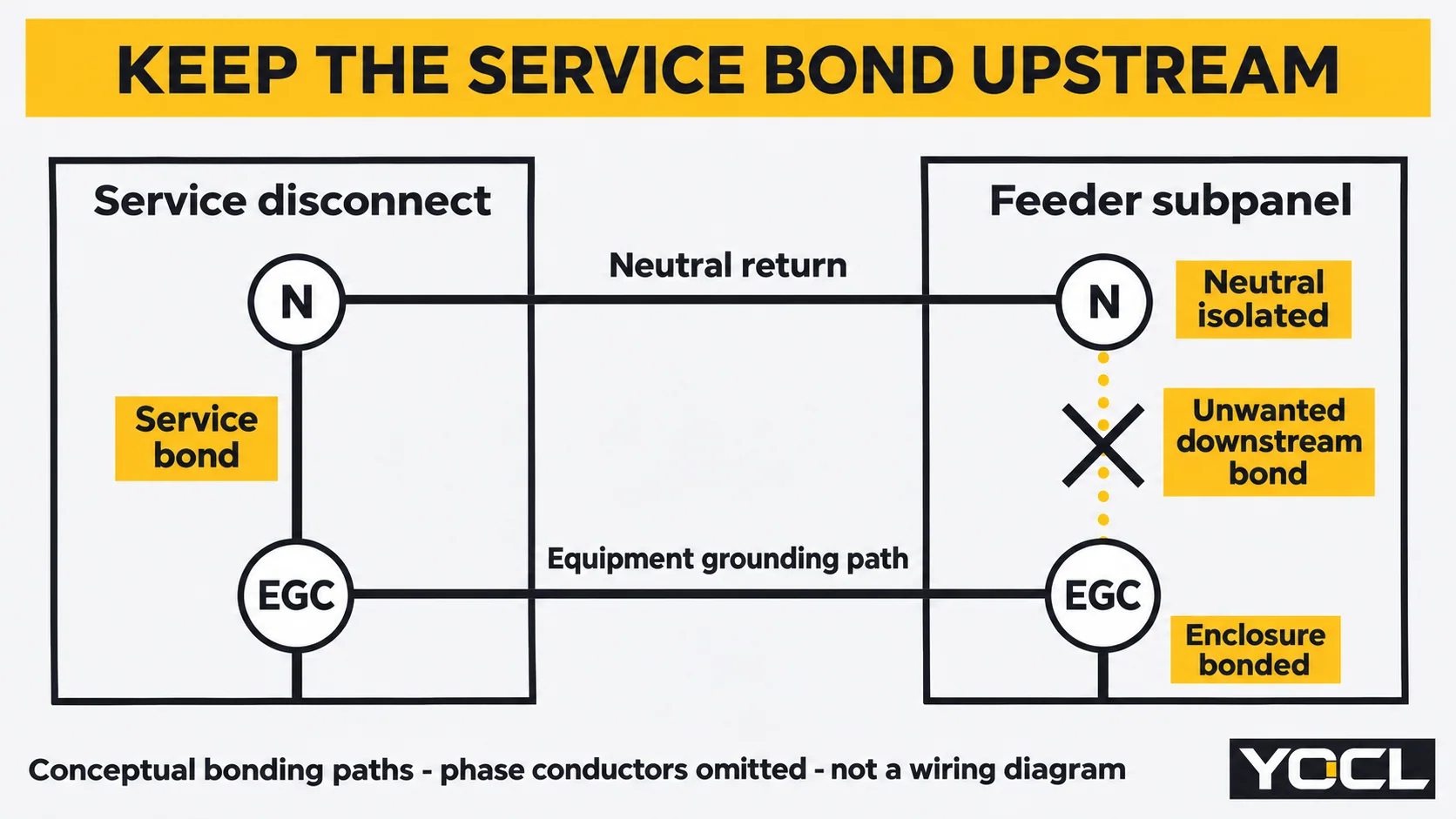
This is why “both bars are grounded somewhere” is the wrong test. The location of their connection determines whether feeder neutral current stays on its intended path or can share the protective network. Removing the intended equipment-grounding connection would not correct the problem; it would compromise protection.
UL’s Panelboard Application Guide explains that downstream neutral bonding creates parallel neutral and grounding paths, including metal raceways. An open neutral can make the consequences more severe. Ground-fault protection can also operate improperly in some arrangements; a GFCI trip is not a necessary symptom or proof of this particular defect. [2, 4]
NEC: the bonding screw trap
Some panelboards can be configured for either service or feeder use. Their identified bonding provision exists because the correct relationship changes with the equipment’s role. Receiving a screw with the cabinet does not mean it belongs in the installed neutral-to-case path.
The relevant question is what that screw or strap connects. In service equipment it can complete the required main bond. In an ordinary feeder subpanel, the same connection would join the isolated neutral to the already bonded enclosure, creating the parallel path described above.
Schneider Electric’s instructions for QO and Homeline load centers used as subpanels explicitly require an insulated neutral assembly and no installed neutral bonding screw. That is an example from those product families, not a claim that YOCL supplies those panel systems or a universal screw-location drawing. [5]
A useful recognition sequence is documentary, not a removal procedure: establish the service-disconnect location, identify the equipment’s neutral assembly, and compare the actual bonding provision with its diagram. Then determine whether neutrals and equipment grounds have been mixed downstream. Any discrepancy requires qualified correction.
The absence of a visible green screw is not proof of isolation. A metal strap, incorrect fastener or conductive connection elsewhere can still bond neutral to the case. Conversely, a green grounding-terminal screw may have a legitimate protective function; colour alone does not identify the neutral bonding jumper.
Not every panel can be converted between roles. UL distinguishes equipment intended only for service use, including factory-bonded-neutral constructions. Removing a visible bond does not establish that such equipment has the insulation or approval needed for feeder use. Its markings and instructions decide. [4]
Likewise, a cabinet called the “main panel” may be downstream from an outdoor service disconnect and need feeder-panel separation. The presence of a main breaker inside that cabinet does not move the service boundary. Have the supply arrangement confirmed rather than classifying the panel by size or nickname.
Outside North America: IEC N and PE are a separate assessment
IEC-based installations use N for neutral and PE for protective earth. In a TN-C-S arrangement, a combined protective-and-neutral conductor, PEN, exists in part of the supply and then separates into N and PE. The IET describes that separation on the installation side. Once separated in the described arrangement, downstream distribution must preserve the separate functions. [6]
That does not make the NEC service-disconnect rule an IEC installation instruction. TN-S already has separate neutral and protective conductors; its source arrangement differs from a customer PEN separation. TT has a different local-earthing context and needs its own installation assessment.
Do not use the presence or absence of a familiar North American green bonding screw as the IEC verdict. Links, terminal arrangements and bonding hardware vary with the equipment and supply design; there is no universal screw convention that replaces the approved N/PE arrangement. Apply the appropriate system documentation and local rules, not a blend of NEC labels and IEC assumptions.
NEC field checklist: what the evidence should show
Use this checklist for a qualified inspection under the applicable safe-access, isolation and verification procedure. It is not an invitation for an owner to remove a dead front. Turning off a panel’s main breaker does not necessarily deenergize its incoming parts or address another supply source.
For the common US single-phase cable-fed example, the feeder has two line conductors, a neutral and an equipment grounding conductor: the familiar four-wire arrangement. This is not a universal conductor count. A different supply configuration or permitted metal-raceway grounding method needs its own review; a photograph showing three insulated conductors does not settle the grounding path.
Under 408.40, the panelboard grounding arrangement connects the equipment-grounding assembly and metal enclosure as required. For ordinary branch-circuit neutrals, 408.41 requires an individual terminal for each neutral. Do not put another neutral or a grounding conductor into that neutral termination. Any special parallel-conductor exception needs the applicable identified arrangement; it is not a normal branch-circuit shortcut. Grounding-conductor combinations depend on the terminal’s markings, not a universal number per hole. [3, 4]
| Check | Expected evidence in an ordinary feeder subpanel | Defect or unresolved condition |
|---|---|---|
| Actual panel role | Supply records establish a feeder downstream of the service disconnect | “Main” label or breaker size is the only basis for classification |
| Neutral isolation | Documented insulating arrangement; no intentional local neutral-to-case connection | Bonding strap, screw or another conducting bridge joins neutral to the case |
| Equipment grounding | Identified grounding assembly has its documented enclosure connection | Protective connection is absent, uncertain or inferred from appearance alone |
| Neutral occupancy | Each ordinary branch neutral has its own terminal | Multiple conductors share a neutral termination without a specifically applicable identified arrangement |
| Ground-terminal occupancy | Conductor combinations match the marked instructions | Shared entries are justified only by available space |
| Feeder paths | Separate neutral and documented equipment-grounding path; four conductors in the stated cable example | Neutral is being used as the downstream enclosure’s protective connection |
| Equipment suitability | Markings permit the actual service or feeder configuration and installed accessories | Factory-bonded service-only equipment is assumed convertible by one screw change |
A qualified person must interpret electrical testing with the circuit arrangement in mind. A continuity indication between neutral and ground can include the intended upstream service bond; by itself it does not locate a local bridge. This article provides no test or disconnection procedure for separating those paths.
What a YOCL bar page can establish
The YOCL neutral and earth-bar category routes the available component forms. YC038 identifies a brass common conductor with steel screws, while the BS page shows a supported neutral-bar form. Use the exact drawing to discuss the bar body, its mounting arrangement and the required insulation or bonding interface.
These are components. Their public product descriptions do not establish a UL-listed panelboard, an approved grounding kit for a particular enclosure or a compliant completed assembly. Do not infer current capacity, tightening requirements or protective continuity from hole count, brass appearance or support colour. The panel manufacturer and responsible electrician must establish compatibility and the required installation evidence. [7]
The resulting inspection record should identify the actual service boundary, the neutral and grounding assemblies, the bonding provision, the feeder grounding method and any discrepancy. Correction belongs with qualified electrical personnel. Simply noting “remove the green screw” can miss a service-only panel, another bridge or incorrectly landed conductors.
FAQ
Can I land neutrals and grounds on the same bar in a subpanel?
No, for the ordinary NEC feeder subpanel described here. Neutral must remain isolated from the equipment-grounding assembly and enclosure. Joining them creates a parallel normal-current return route through protective conductors and metalwork. A permitted service bond upstream does not justify another bond downstream. Special supply arrangements require their own assessment.
My subpanel came with a green bonding screw installed. Is that wrong?
If that screw actually bonds the neutral assembly to the case in an ordinary feeder application, the configuration is wrong. First confirm the panel’s actual role and the screw’s identified function: not every green screw is the neutral bonding jumper. Have a qualified electrician assess the markings and complete arrangement rather than treating removal alone as the repair.
Why do some panels have only one bar?
Service equipment can use a permitted common neutral/grounding arrangement, subject to its terminal identification and individual neutral-termination requirements. Existing installations can also have older configurations, including three-wire arrangements needing separate review. One visible bar does not prove the panel is service equipment or that an old arrangement is acceptable today. It is not a template for a new feeder installation.
What happens if neutral and ground are bonded in two places?
A second bond along the service-to-subpanel feeder can let normal neutral current divide onto the equipment-grounding path and bonded metalwork. This is the objectionable-current concern described here; it can create shock, heating and protection problems. The amount and symptoms depend on the paths and load. A quiet, functioning panel is not proof that the extra bond is harmless.
How can I tell which bar is the neutral bar and which is the earth bar?
In an ordinary NEC feeder panel, identify the insulated neutral assembly and the separately bonded equipment-grounding assembly from the equipment diagram, mounting and conductor assignments. White/gray versus bare/green conductors are clues, not proof of correct wiring. A hidden bridge or mixed conductors can mislead visual identification. IEC N/PE arrangements require their own system documentation; have uncertain findings assessed by a qualified electrician.
Sources
- Mike Holt, Article 250: Grounding and Bonding, based on the 2017 NEC, Part 1. Service fault path and main bond, including the cited 250.24(B) and 250.28 numbering.
- Mike Holt, 2014 NEC grounding and bonding sample, printed pp. 50-53. Objectionable current and load-side neutral-to-case connections, 250.6 and 250.142(B).
- Mike Holt, Switchboards and Panels, January 29, 2010, based on the 2008 NEC. Panelboard grounding, bonding provisions and neutral terminals: 250.24(A)(5), 408.40 and 408.41. Dated commentary, not current adopted code text.
- UL Solutions, Panelboard Application Guide, factory-bonded neutrals, equipment grounding terminal bars and wiring terminals. Assembly and marking distinctions; no YOCL certification inferred.
- Schneider Electric, QO and Homeline load centers used as subpanels, FAQ FA96427, modified October 7, 2024. Original instructions for those product families only.
- IET, Broken PEN, March 2021. TN-C-S/PEN separation context; no NEC rule transferred into IEC installations.
- YOCL ELECTRIC, YC038 and BS001-0609 product information linked above, reviewed November 10, 2026. First-party component descriptions and exterior references, not panel certification.