
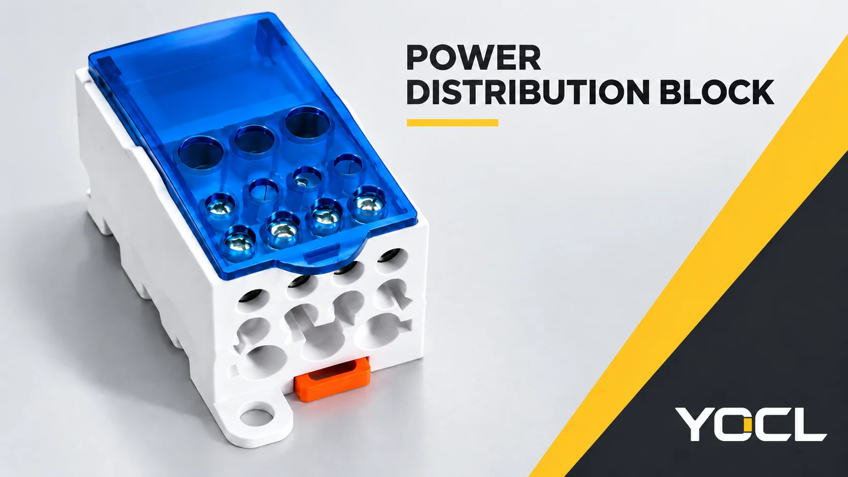
A power distribution block provides a supported, insulated connection between an incoming supply conductor and several outgoing conductors. Within a common pole, the designated connection points are electrically joined; separate poles remain insulated from one another. A distribution-only block makes the connection. It does not regulate voltage, divide current equally or replace circuit protection.
Read the device through three questions: Which points are connected? Which conductor belongs at each position? What duty do the declared ratings cover? A hole count or headline ampere value cannot answer all three.
Inputs, Outputs and Poles Describe Different Things
An input is the connection for the incoming conductor. An output, also called a tap-off connection, serves an outgoing conductor. A pole identifies an electrically common path that must remain separated from other poles. One pole can therefore have several outputs without creating several independent supplies.
The public scope of UL 1953, Outline of Investigation for Power Distribution Blocks, §§1.2–1.3, describes connectors on an insulating base, incoming and tap-off provisions, and separation between polarities and the mounting surface. This is a useful structural reference within its stated U.S. National Electrical Code (NEC) application scope; it does not establish a YOCL model’s certification.
The basic orientation is:
Incoming conductor → common connection within one pole → designated outgoing conductors.
The connected points belong to the same electrical node. Different outgoing circuits can have different loads and their own protective arrangements. An output position is a connection point, not an individually protected channel. Likewise, connecting different supply potentials to a common pole would join those potentials, rather than keep them isolated.
Branch count does not divide the current
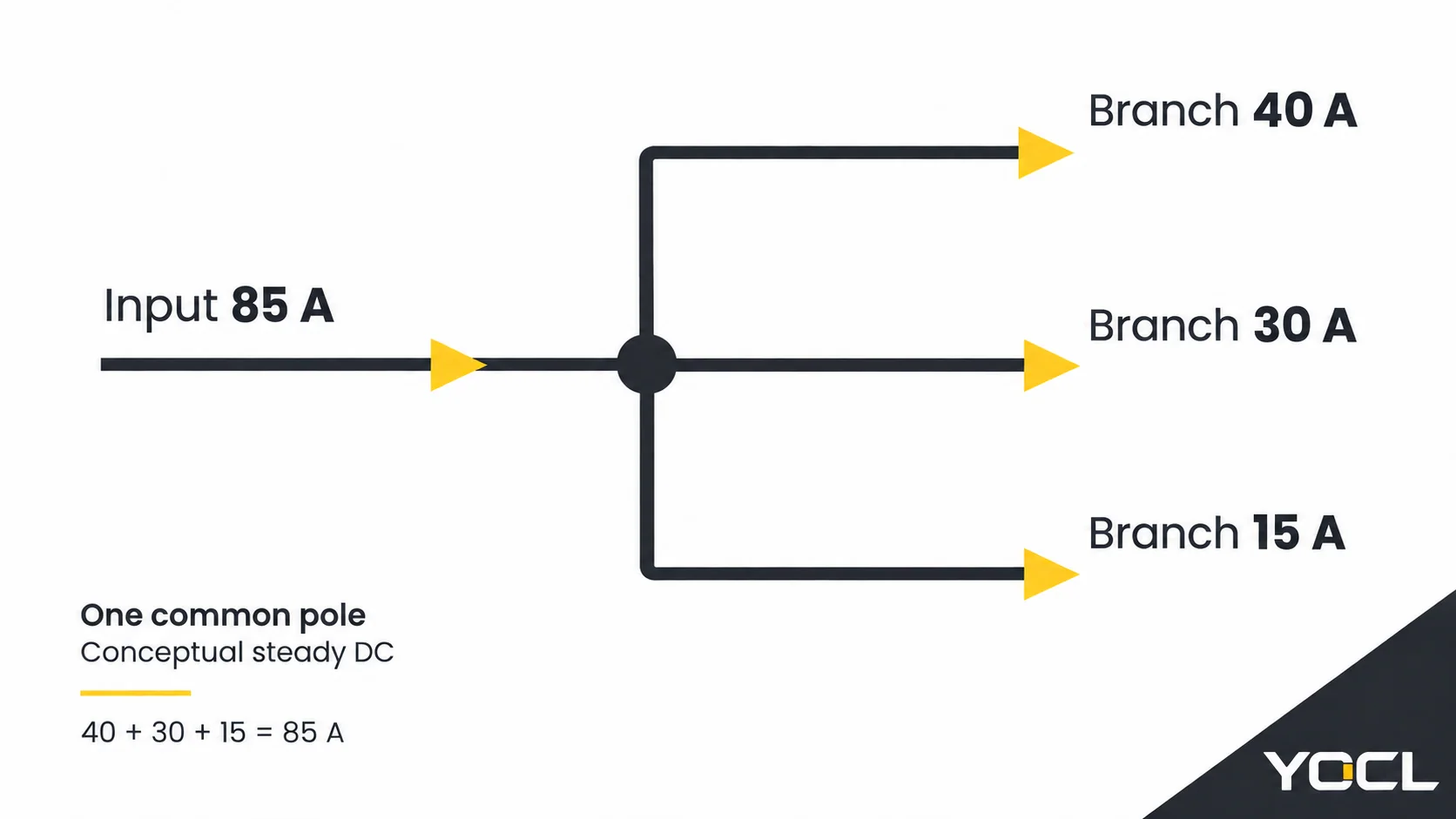
OpenStax’s explanation of Kirchhoff’s junction rule states that current entering a node equals current leaving it. The number of outgoing positions does not determine each branch current.
For an illustrative steady direct-current (DC) node, assume three simultaneous outgoing currents of 40 A, 30 A and 15 A, with no other connected branch. The incoming current is 40 + 30 + 15 = 85 A. It is not automatically split into three equal shares. This is circuit arithmetic, not a UKK rating test or a conductor/protection sizing result; it is not an instruction to add arbitrary alternating-current root-mean-square (AC RMS) readings.
A mounting rail does not establish the circuit
A DIN rail supports the mounted components. Adjacent ordinary feed-through terminals are not electrically joined merely because they share that rail; their documented connection or bridge arrangement determines commoning. The terminal-block connections and DIN rail accessories guide explains that separate task.
Product names can overlap, so inspect the circuit function and applicable documentation. UL 1953’s public §1.4 explicitly excludes terminal blocks covered by UL 1059. Calling a product a “distribution block” does not, by itself, establish which evaluation applies.
Read the Connection Schedule: A UKK-250A Example
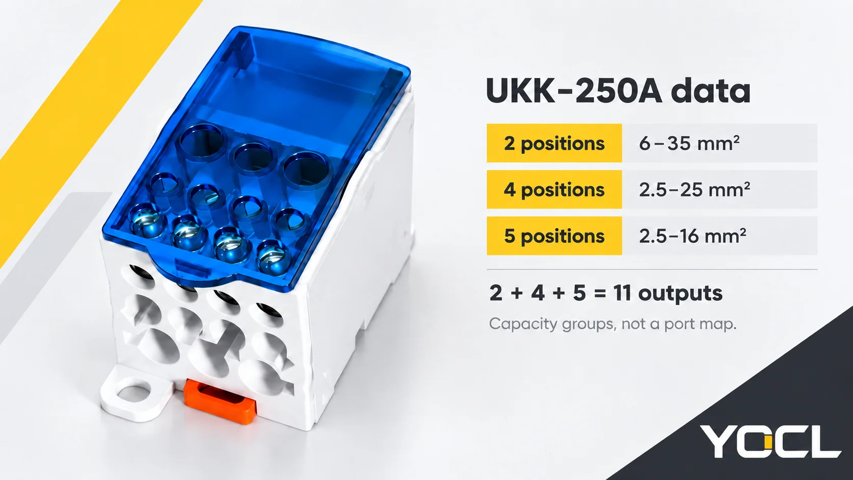
YOCL’s UKK is a single-pole, screw-connected distribution-block family. The UKK model and connection-capacity tables provide a clear example with UKK-250A:
| UKK-250A field | Published entry |
|---|---|
| Rated current | 250 A |
| Rated voltage | 690 V |
| Connection arrangement | 1 input / 11 outputs |
| Input specification | 120 mm² × 1 |
| Output capacity group 1 | 2 positions, each 6–35 mm² |
| Output capacity group 2 | 4 positions, each 2.5–25 mm² |
| Output capacity group 3 | 5 positions, each 2.5–16 mm² |
These are manufacturer declarations, not measurements from an installation. The three different size groups total eleven output positions.
A 25 mm² conductor falls within groups 1–2, above group 3’s upper bound. That comparison narrows the relevant positions; it does not confirm conductor construction, preparation, finished-end fit or allowable current. A numbered model drawing is still needed to locate the correct physical connection.
The input entry is not a minimum-to-maximum acceptance range. Do not fill in a smaller permissible input size by analogy with another model. Nor can screw-access holes be counted as additional conductor positions. Use the exact connection schedule and drawing together.
What the Ratings Establish—and What Still Needs Documentation
Each field answers a different question. A large ampere value cannot settle voltage duty, wire compatibility or fault performance.
| Field | Question it helps answer | Evidence still needed for the application |
|---|---|---|
| Rated current | What current capability is declared for this model? | Applicable rating conditions and the proposed simultaneous load duty |
| Rated voltage | What voltage duty is declared? | The specified AC/DC use and relevant insulation/application conditions |
| Conductor capacity | Which stated size entry or range applies at this position? | Material, construction, conductor count and permitted preparation |
| Connection instructions | How is the permitted conductor retained? | Model-specific stripping, tightening and preparation instructions |
| Mounting and covering | How does the component fit the equipment? | Drawing, fixing/cover requirements and space for conductors |
| Short-circuit evidence | What fault duty can the documented arrangement support? | Applicable short-circuit rating or withstand data, voltage and protective conditions |
Normal current is not an allowance for every output
The model’s current entry is not a separate rating for every output. Multiplying the headline current by the number of outputs does not create additional capacity. Review the shared incoming path, the simultaneous branch duty and the applicable rating conditions.
Similarly, a conductor-area entry cannot establish a branch’s allowable current on its own. That question also belongs to the conductor, termination and equipment requirements. The UKK example explains how to read fields; it does not complete that design check.
Wire fit includes material, construction and preparation
A wire can fall within a nominal area range while the proposed termination remains undocumented. Check solid versus stranded construction, the permitted prepared end and the number of conductors at each clamp. The conductive body’s material is not proof that the connection accepts a conductor made from the same metal.
For a scoped regulatory example, U.S. workplace OSHA 1910.303(c)(1)–(2) requires connections to be identified for conductor material and terminals for multiple conductors or aluminium to be identified accordingly. This does not approve a particular UKK conductor combination.
Where ferrules are proposed, the single and twin ferrule connection requirements help distinguish the prepared-end arrangements. A twin ferrule is not automatic permission to put two wires into a distribution-block position.
Fault duty belongs to a separate review
A distribution-only block does not open a fault. Its normal-current declaration cannot establish a short-circuit current rating (SCCR) or replace the protection review. In its U.S. workplace scope, OSHA 1910.303(b)(4)–(5) distinguishes equipment interrupting duty and coordination involving component short-circuit ratings and protective devices.
For the actual panel, obtain the applicable fault-current evidence and any specified protective conditions. The public UKK table reviewed here supplies no SCCR value. That is a missing document field, not permission to assign a default value or a finding that the product failed a test. Component data also does not verify the completed equipment arrangement.
Choose the Next Document by the Question Still Open
Use the remaining question to choose the next resource, rather than turn this overview into a wiring or sizing procedure.
| Remaining question | Next resource | Information to carry forward |
|---|---|---|
| Which connection is common, isolated or bridged? | Exact block circuit/terminal drawing; the terminal-block guide above for terminology | Pole arrangement and intended circuit functions |
| Where does each conductor belong? | Exact UKK connection schedule and numbered drawing | Size, material, construction and prepared end for each position |
| Is a single or twin prepared end permitted? | Receiving-device instructions and the ferrule comparison above | Original wire count and finished-end arrangement |
| Does the model fit the required electrical duty? | Model rating documentation and applicable equipment requirements | Current, voltage, AC/DC duty and installation conditions |
| Does the panel meet its fault requirements? | Equipment assessment and component/protection documentation | Available fault current and documented coordination |
For family evaluation, the YOCL power distribution block range provides the product route. Send the exact model, conductor-position schedule, quantity and known circuit duty when requesting its supporting documents. That keeps the enquiry tied to the connection and evidence you actually need.
References
- UL Standards & Engagement — UL 1953: Outline of Investigation for Power Distribution Blocks, Edition 8, November 21, 2024; public scope §§1.1–1.4 only.
- OpenStax, Rice University — University Physics Volume 2, §10.3: Kirchhoff’s Rules; junction rule, equation 10.4 and its explanation.
- YOCL product information — UKK DIN Rail Power Distribution Blocks; UKK-250A model and conductor-capacity declarations, checked October 7, 2026.
- U.S. Occupational Safety and Health Administration — 29 CFR 1910.303: General, §§(b)(4)–(5) and (c)(1)–(2); scoped connection and fault-coordination requirements.