
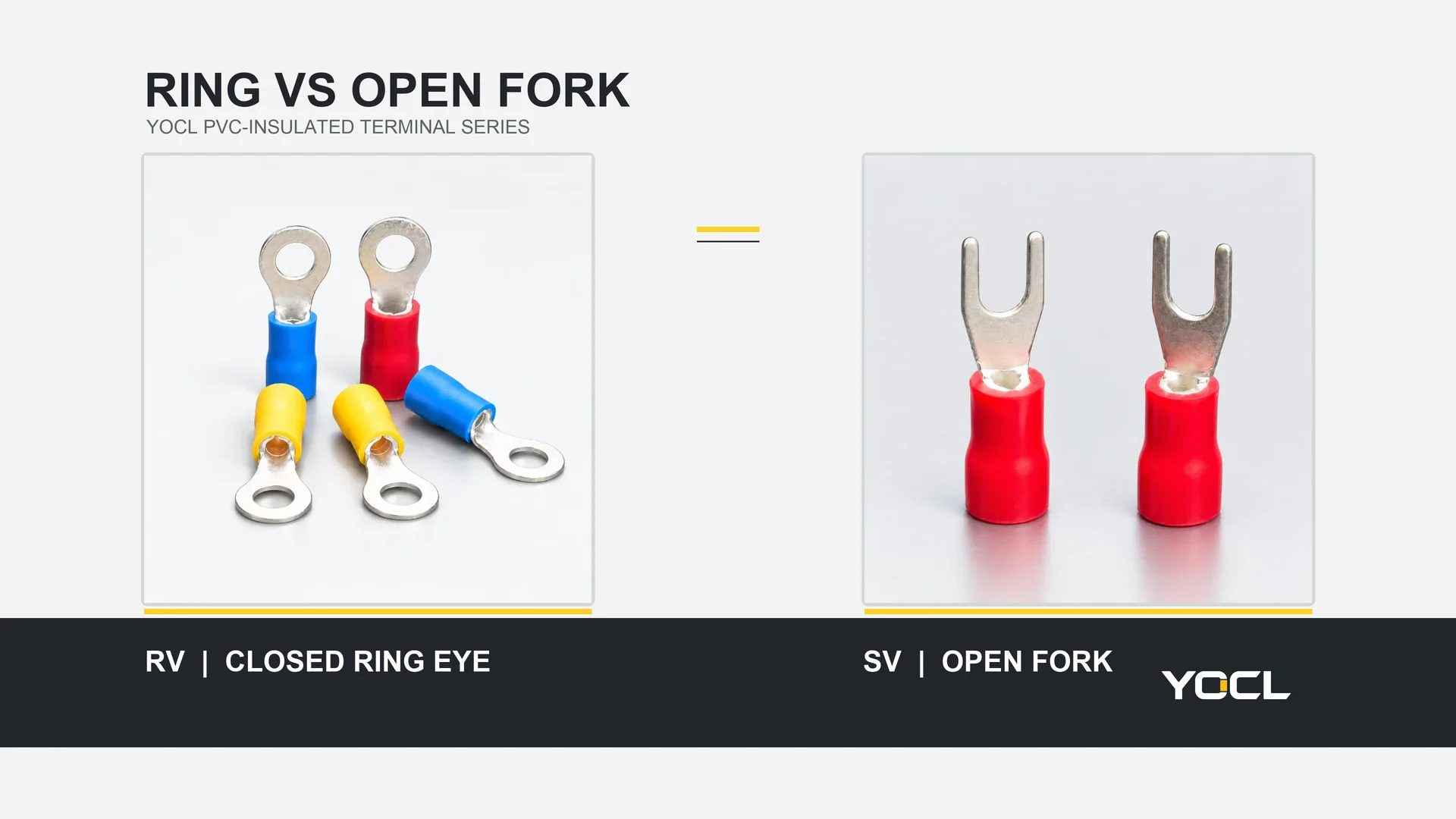
Choose a ring when the connection needs a closed eye around a screw or stud and the required fastener removal is acceptable for service. Consider an open-fork spade when the receiving terminal expressly permits it and a technician needs to withdraw the wire end from under a loosened fastener. A ring stays around a present fastener shank if the clamp loosens; it does not preserve contact pressure or make a loose electrical joint acceptable. A spade has a lateral escape path, but an approved screw, washer or retaining feature may be designed to constrain it. The exact equipment connection decides whether either terminal is suitable.
This comparison concerns an open-fork tongue for a bolted or screw-clamped connection. “Spade” can also be used loosely for a flat blade or quick-disconnect contact; that is a different mating interface. Identify the drawing before comparing parts. YOCL’s crimp-terminal overview separates these contact styles.
Decide Against the Same Screw Connection
Hold the conductor, stud/screw, contact location and required electrical duty constant. Compare the contact geometry and the service operation, then check whether the receiving equipment permits the result.
| Connection condition | Ring: closed eye | Open-fork spade | Bounded decision |
|---|---|---|---|
| Screw or nut remains through the terminal while clamp force falls | Eye remains mechanically around the shank; electrical contact can still become poor | Fork can potentially move out through its open mouth, depending on washer/head/lip geometry | Ring supplies a more captive shape, not a guarantee against a loose joint |
| Wire end must be removed for planned service | Fastener or nut normally must be removed enough to clear the closed eye | Withdrawal under a loosened fastener may be possible if the terminal design and access permit it | Spade may reduce disassembly, but only on an approved connection with a clear withdrawal path |
| Screw cannot be backed out or washer/lip blocks side entry | Closed eye may be impossible to install without hardware disassembly | Open fork may also be unable to enter or seat | Check the real hardware; neither shape is automatically workable |
| Nearby wires or barriers restrict sideways movement | Ring can be placed over a released stud if there is vertical access | Fork may need more lateral approach and exit space | Compare the actual wire route, cover and tool clearance |
| Connection instructions specify one tongue form, hardware stack or torque | Use only if that specification includes the chosen ring model | Use only if it includes the chosen fork model | Equipment instructions override a generic geometry preference |
| Neither terminal/tool/receiving combination is documented | Do not assume acceptance | Do not assume acceptance | Choose neither until the missing evidence is obtained |
The table describes relative mechanical behavior at one connection point. It does not rank contact resistance, vibration endurance, current capacity or certification. Those are properties of an evaluated terminal, crimp, fastener and equipment assembly—not of the word “ring” or “spade.”
What “Retention” Means When a Fastener Loosens
Separate three states that are often collapsed into one claim:
- Tightened and correctly assembled. The screw or nut and its contact surfaces provide the intended clamp. Both ring and fork can serve where the receiving device allows them, their dimensions fit, and assembly instructions are followed. Neither tongue shape compensates for a mismatched crimp or incorrect fastener assembly.
- Loosened but still passing through the contact. A closed ring cannot move sideways off that shank without crossing metal; an open fork can leave through the gap between its tines if the hardware and wire forces allow that path. This is a capture difference. Either connection may have inadequate electrical contact after clamp force is lost.
- Fastener removed or no longer crossing the contact. The ring’s geometric capture has ended. It can move away from the mounting point, just as a fork can. A screw that backs fully out is not made captive by the terminal eye.
The second state is the reason ring terminals are often preferred where unintended lateral release would matter. It must not be described as a safety rating. If a connection repeatedly loosens, the engineering action is to diagnose and correct the fastener, surface, torque, mechanical support or application problem under the equipment maker’s instructions. Replacing a fork with a ring without addressing that cause only changes what remains physically attached after clamping has already failed.
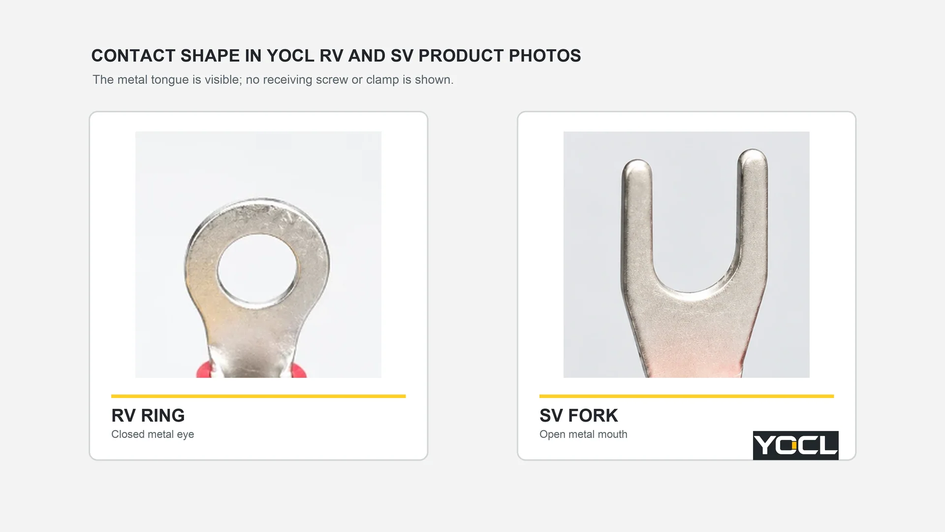
Retaining details can change the fork’s behavior. A washer larger than the fork opening, a terminal lip, a captive screw or a shaped pressure plate may constrain vertical and sideways movement in the specified assembly. Conversely, a plain screw head over a fork with little contact overlap can leave little margin if the clamp relaxes. Do not add an arbitrary washer to “convert” a fork into a ring-like connection: washer type, order, contact area and tightening requirements belong to the receiving equipment design.
Service Access Is a Geometry and Workflow Question
The spade’s open mouth can save a fastener-removal step when the screw may be loosened while remaining captive in the device. This is useful where fully removing a small screw risks losing it or disturbing adjacent terminations. Yet “loosen and slide out” is only possible when the screw head or washer leaves enough vertical clearance, the fork can travel sideways, and the wire can follow that movement without stressing the crimp or adjacent conductors.
A ring requires the closed eye to pass over a released screw or stud. That may mean removing a nut, lifting a washer, or fully withdrawing a screw; the exact action depends on the hardware. A ring can be preferable even in a serviceable assembly when infrequent disconnection and positive mechanical capture matter more than a quick side exit. The extra removal step should be planned in the maintenance procedure rather than discovered when the enclosure is crowded.
Map the access before selecting the tongue:
| Access question | Why it matters |
|---|---|
| Can the fastener be safely and completely removed if a ring is selected? | A captive screw may not clear the ring eye; a hidden nut may be inaccessible. |
| Is there a straight, unobstructed side path for a fork? | A barrier, adjacent terminal, cover rib or rigid wire bend can block withdrawal even when the screw loosens. |
| What holds the contact while the screw is loosened? | Washer and terminal geometry determine whether the fork can move or be lifted out as expected. |
| Can the correct tool reach the fastener for reassembly and verification? | A theoretically removable tongue is not useful if the required tightening or inspection tool cannot be applied. |
| Will the wire remain supported during repeated service? | Sideways levering at the tongue or barrel can damage a crimp; plan a wire route that permits the specified motion. |
These questions are particularly important in compact control cabinets and tightly populated equipment. Do not infer service convenience from a catalogue photograph alone. Inspect the actual screw, terminal landing, washer stack, neighbouring conductors and cover clearance in the final assembly.
For covered U.S. workplaces, OSHA 29 CFR 1910.333 addresses de-energization, lock/tag and verification before work on or near exposed electrical parts. Other jurisdictions have their own requirements. A spade’s shorter mechanical removal sequence is not permission to disconnect it live; follow the applicable work procedure and the equipment manufacturer’s instructions.
Same Wire and Opening: YOCL RV 1.25-4S vs SV 1.25-4S
YOCL’s published model tables provide a concrete comparison without inventing a test. The RV 1.25-4S ring terminal and SV 1.25-4S fork terminal are both in PVC-declared 1.25 groups for 0.5–1.5 mm² conductors. Both list d2 = 4.3 mm, but the RV drawing labels d2 as the ring hole, whereas the SV drawing labels it as the fork opening.
| YOCL catalogue field | RV 1.25-4S ring | SV 1.25-4S fork | Selection implication |
|---|---|---|---|
| Declared conductor group | 0.5–1.5 mm² | 0.5–1.5 mm² | Shared group does not establish a shared crimp tool or equipment approval. |
| d2 | 4.3 mm ring hole | 4.3 mm fork opening | Same nominal opening dimension, different retention path. |
| B, contact width | 6.6 mm | 6.4 mm | Check the actual landing and neighbouring clearance. |
| F, drawing dimension | 6.3 mm | 6.5 mm | Check where the contact sits under the hardware. |
| L, overall length | 19.6 mm | 21.2 mm | Check wire bend and enclosure clearance. |
Values are YOCL catalogue declarations, not finished-crimp measurements or comparative performance results. The drawing labels identify different physical features, so the identical d2 values are not interchangeable-interface proof. The RV eye must pass over the intended stud or screw; the SV slot must enter beneath the intended clamp with adequate contact overlap and permitted retention. Both must fit the actual hardware stack and wire route.
This model pair shows a key purchasing trap: ordering by conductor range and “M4-compatible” shorthand alone can miss contact width, tongue reach and barrel clearance. The two products also need their own conductor preparation and applicable crimp-tool instructions. A catalogue colour group is not a tooling instruction or a certification mark.
The YOCL PVC-insulated terminals family page explicitly routes ring and fork selection through stud diameter and space around the screw connection. It also asks for the compatible die and crimping instructions for the chosen model. Use that information to shortlist a product, not to declare a ring-to-fork substitution automatically approved.
Check the Whole Connection Before Substituting
Start at the receiving equipment, not at the shape catalogue. The screw terminal may be designed for a bare conductor, a specific ring tongue, a fork with a captive screw, or another preparation. Its instructions can constrain tongue thickness, number of terminals under one fastener, contact area, washer use and tightening method. If the manufacturer does not permit a crimp tongue or the proposed form, neither “better retention” nor easier maintenance authorizes it.
For a candidate ring or fork, verify the following as one combination:
- Receiving point: exact equipment/terminal model, allowed prepared conductor and contact form, screw/stud diameter, head or washer geometry, permitted stacking and fastening instructions.
- Wire and barrel: conductor material, nominal cross-section, strand construction, insulation diameter and the terminal model’s declared wire range. Check whether the pre-insulated barrel actually fits the prepared wire.
- Crimp process: specified terminal–wire–tool–die combination, strip length and completion/inspection method. A closed ring can still fail at its wire crimp. The public IEC 60352-2:2024 abstract describes solderless crimped-connection evaluation under mechanical, electrical and atmospheric conditions; it does not approve a particular YOCL combination or choose ring versus fork.
- Mating geometry: actual d2 opening or hole, tongue width and length, contact thickness, landing size, insulation-barrel clearance and nearby barriers. Do not rely on nominal screw size alone.
- Service motion: required fastener-removal or side-withdrawal path, tool access and wire slack in the assembled equipment. Confirm whether the planned operation can be repeated without bending the tongue or pulling on the crimp.
- Evidence: the current drawings and instructions for both products and receiving equipment, plus any application-specific approval or test record the project requires. If one document is missing, mark the substitution unresolved rather than promising equivalence.
The crimp and the mating joint are separate interfaces. A good barrel crimp does not prove adequate contact beneath a screw; a correctly torqued screw does not repair a damaged wire-to-barrel crimp. Likewise, the PVC sleeve over a barrel does not insulate the exposed ring or fork contact. For sleeve-material and coverage questions, see PVC vs nylon vs non-insulated crimp terminals.
Apply the Tradeoff to Typical Decisions
Connection subject to a required closed-eye rule. If the equipment or project specification explicitly requires a ring tongue, use a ring model that also meets the wire, hardware and crimp requirements. Do not substitute an open fork for faster service. This includes any protective or bonding connection only when the actual equipment instructions and applicable requirements specify that arrangement; there is no universal rule that every grounding point accepts any ring.
Frequent planned disconnection at a captive screw. A fork is a candidate when the terminal is specifically designed or documented for an open-fork tongue and side access exists. Its convenience comes from the permitted service operation, not an assumed electrical superiority. Record how the fastener is loosened, how the fork is re-seated and how assembly is verified.
Possible fastener loosening or wire movement. The ring’s closed eye removes one lateral escape path while the fastener shank remains through it. It does not make the joint electrically sound after loss of clamp force. Establish the correct support, fastener design and maintenance method rather than treating a ring as a cure for loosening.
Narrow landing with a nearby wall. A fork may need lateral travel that the enclosure does not provide; a ring may need vertical hardware removal that the cover does not permit. Either can be the wrong part even when conductor and nominal stud sizes match. A drawing and physical clearance review decide.
Only a product photo or colour is available. Choose neither yet. Request the full terminal model, drawing, approved receiving connection and crimp instructions. The question is not which shape seems familiar but which complete connection can be documented.
For a YOCL enquiry, supply the conductor specification, receiving screw/stud model, required ring or fork arrangement, space around the connection, service frequency and expected quantities. The PVC-insulated terminal range routes to the model tables; ask for the selected drawing and tooling instructions before changing an existing connection.
References
- U.S. Occupational Safety and Health Administration — 29 CFR 1910.333, Selection and Use of Work Practices. U.S. workplace electrical-service scope.
- YOCL product information — RV Pre-Insulated Ring Terminal. RV 1.25 group construction and RV 1.25-4S declared dimensions, accessed October 15, 2026.
- YOCL product information — SV Pre-insulating Fork Terminal (TU-JTK). SV 1.25 group construction and SV 1.25-4S declared dimensions, accessed October 15, 2026.
- YOCL product information — PVC-Insulated Terminals Manufacturer. Ring/fork product routing and selection fields, accessed October 15, 2026.
- IEC — IEC 60352-2:2024, Solderless Connections, Part 2. Official public abstract for crimped-connection scope; full standard not consulted.