
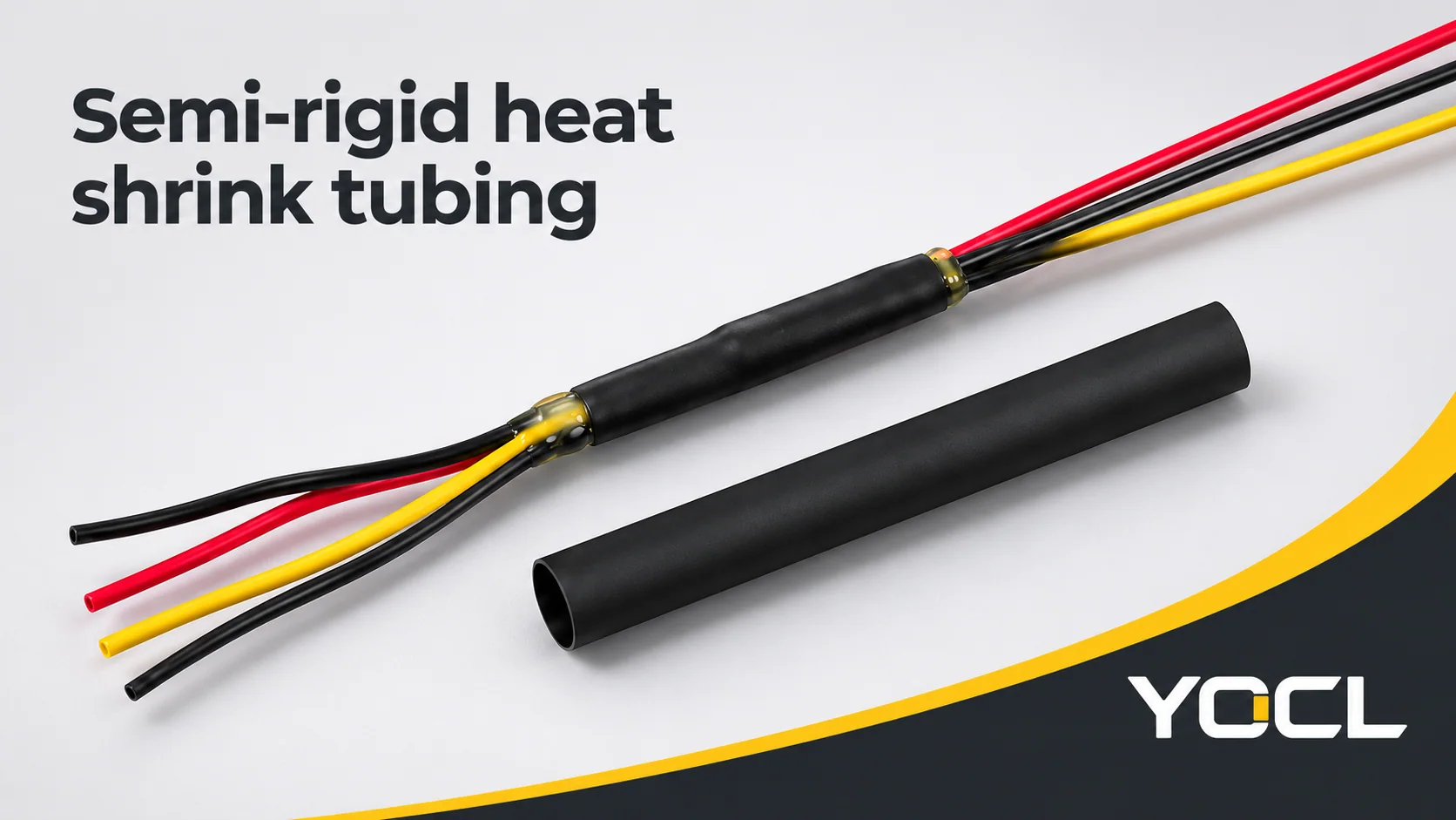
Choose semi-rigid heat shrink tubing when a harness joint needs a cover that stays stiff and wear-resistant while retaining an adhesive seal. Choose flexible dual-wall tubing when the covered section must keep flexing. Both choices can have two walls and a nominal 4:1 shrink ratio: the deciding variable is the recovered outer wall’s rigidity.
YOCL’s HSWH-B4X product information makes that distinction directly. It pairs a semi-rigid polyolefin outer layer with a hot-melt adhesive lining and identifies automotive harness joints, branches and connectors as its application. Its own comparison lists HS4X with a flexible polyolefin outer layer and the same adhesive-lined construction. The practical question is whether the protected section should hold its shape or accommodate movement.
Separate wall count, shrink ratio and rigidity
Three selection axes answer different questions. Confusing them can produce a sleeve that fits and seals but behaves incorrectly in the harness route.
| Selection axis | Question it answers | What it does not establish |
|---|---|---|
| Wall count and lining | Is an adhesive sealing interface part of the construction? | Whether the recovered outer wall is flexible or semi-rigid |
| Shrink ratio | What diameter transition can the tubing accommodate, subject to actual size limits? | Adhesive lining or recovered-wall stiffness |
| Rigidity | Should the covered section remain shape-holding or stay flexible? | A mechanical load rating |
For the adhesive decision, use the single-wall versus dual-wall explanation. That page explains the sealing interface and why close recovery alone does not establish a seal.
For diameter transitions, the 2:1, 3:1 and 4:1 comparison covers ratio selection. Here, hold the ratio and wall count constant to isolate rigidity. The anchor page compares HSWH-B4X and HS4X as 4:1 adhesive-lined constructions, both with a −45 °C to +125 °C operating range. Their outer-wall construction and application emphasis differ.
Rigidity is the less conspicuous third question: after the sleeve recovers, what shape must this section maintain during service? Answer it before treating two otherwise similar constructions as substitutes. The heat shrink tubing overview provides the broader terminology if needed.
Where a stiff outer wall earns its place
The B4X page declares wear resistance and mechanical protection from its semi-rigid outer layer. Its hot-melt lining provides the environmental sealing function against water, moisture and corrosion. Those functions address different parts of the same harness-covering problem.
Rubbing or contact with surrounding components
A fixed harness joint may sit where its covering can contact nearby components. B4X is a candidate when the requirement is a semi-rigid, wear-resistant outer covering around that joint. Identify the contact area on the harness drawing so the protected length addresses the actual location.
Wear resistance is a declared property here, without a published abrasion-life figure. It supports considering the construction for this problem; it does not quantify how long a particular rubbing condition can continue.
Branches and breakouts
At a branch or harness transition, the useful feature is a covered region that holds its recovered shape while the wires continue along their intended routes. The selection concerns the local protected run and the space it occupies.
A branch is also a geometry problem: the tubing must pass over the relevant feature and recover around the intended cable or bundle. A stiffness preference cannot compensate for a shape that the selected size cannot cover appropriately.
Connector and terminal exits
The anchor lists connector and terminal protection. A shape-holding cover can be appropriate at an exit where the harness layout calls for a straight protected section. Check the largest connector feature for passage, then the smaller landing region for recovery.
Keep the sleeve’s role separate from the electrical connection. Choosing the covering does not select or validate the underlying terminal, splice or connector.
Repairs in exposed runs
The page also lists cable repairs and moisture-sensitive wiring. Consider B4X when the repaired area needs both environmental sealing and a semi-rigid wear-protective covering. Determine whether the repaired section is fixed or moves in service before choosing it.
The location alone does not settle the choice. A repair on a moving section still needs the flexibility decision below, even when moisture protection is required.
Where semi-rigid is the wrong default
A recovered semi-rigid wall holds its shape. That is useful at a fixed breakout or connector exit, but works against a layout in which the covered joint itself must repeatedly flex or follow a tight bend.
Use flexible dual-wall construction as the starting alternative for those sections. In the anchor page’s construction comparison, HS4X has a flexible polyolefin outer layer for general cable insulation and environmental sealing. Switching outer-wall behaviour does not inherently mean giving up the hot-melt lining or selecting a different ratio class.
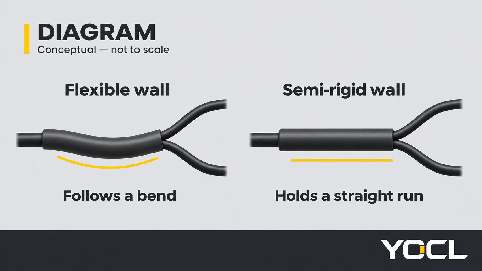
YOCL publishes no bend-radius or flex-life figures for B4X. The comparison is qualitative, so it cannot set a minimum bend, predict motion cycles or establish a measured flexibility difference. Separate the section intended to stay straight from the section expected to move. If the covered region itself must move, do not specify the stiff construction merely because its diameter fits.
Read the HSWH-B4X product fields properly
For semi-rigid heat shrink tubing, the construction decision comes first; the exact size and available space still decide whether the candidate is usable. The following six rows reproduce the current B4X dimension table using millimetre designations. All six sizes are supplied in 1.22 m lengths.
| Size (supplied I.D. designation) | Supplied I.D. | Max. I.D. after recovery | Recovered total wall | Adhesive layer | Standard length |
|---|---|---|---|---|---|
| 4.0 mm | ≥4.0 mm | ≤0.95 mm | 1.40 ± 0.30 mm | 0.60 ± 0.20 mm | 1.22 m |
| 6.0 mm | ≥6.0 mm | ≤1.27 mm | 1.70 ± 0.30 mm | 0.80 ± 0.20 mm | 1.22 m |
| 8.0 mm | ≥8.0 mm | ≤1.65 mm | 2.00 ± 0.30 mm | 0.95 ± 0.20 mm | 1.22 m |
| 10.0 mm | ≥10.0 mm | ≤2.00 mm | 2.30 ± 0.40 mm | 1.10 ± 0.20 mm | 1.22 m |
| 12.0 mm | ≥12.0 mm | ≤2.41 mm | 2.45 ± 0.40 mm | 1.20 ± 0.20 mm | 1.22 m |
| 18.0 mm | ≥18.0 mm | ≤4.45 mm | 2.60 ± 0.40 mm | 1.34 ± 0.30 mm | 1.22 m |
Read the limits, not just the size name
Inside diameter, or I.D., is the bore. Supplied ≥ gives the stated minimum before recovery; recovered ≤ gives the maximum after recovery. These are limits, not two exact installed dimensions.
The supplied bore must pass over the largest component. The maximum recovered bore must suit the smaller cable or bundle requiring sealing. Do not calculate a replacement recovered limit by dividing the size designation by four: the page calls the ratio nominal and lists the recovery limits individually. Its inch/mm labels are nominal designations; the mm limits above are the selection data.
The page’s own 10.0 mm example reads: supplied I.D. ≥10.0 mm, maximum recovered I.D. ≤2.00 mm, recovered total wall 2.30 ± 0.40 mm, and adhesive layer 1.10 ± 0.20 mm. This is a worked reading of a catalogue row, not approval for an unspecified connector and cable. Actual passage, landing geometry and available space remain required inputs. For the general diameter-selection method, use the heat shrink tubing size chart.
Account for wall, lining and stock length
Across the range, nominal recovered total wall increases from 1.40 mm to 2.60 mm, and nominal adhesive thickness from 0.60 mm to 1.34 mm. Keep the row-specific tolerances. “Total wall” already includes the adhesive layer; do not add the adhesive column again as another wall allowance.
These fields matter where a covered joint sits near surrounding components. A size that passes the connector still needs room after recovery. Check the page’s −8% to +8% axial change, reported under ASTM D2671, against available space and required coverage as well.
The 1.22 m supply format is an ordering and production-planning fact. Distinguish the stock length from the protected length needed at each joint. The detailed cutting and heating workflow belongs in the cable-splice application guide.
Keep recovery and operating temperatures separate
B4X specifies an initial shrink temperature ≥70 °C, full shrink temperature ≥125 °C, and operating range −45 °C to +125 °C. The first two describe recovery during installation; the last describes service conditions. They are not interchangeable and do not provide a heat-gun setting.
The page also declares UV resistance, RoHS, standard black and custom colours. These are series declarations, not substitutes for the geometry and movement checks.
What the page does not declare
The B4X page declares no voltage rating or UL/CSA listing. Semi-rigid is not a load rating: no pulling-load, impact or crush rating is declared. Its flame result is Pass (ASTM D2671), not a named flame class. The published adhesive peel entries lack identified substrates, so they cannot support a substrate-specific bond comparison. These omissions should stay omissions when specifying the cover.
The distinction between shape-holding protection and a rated mechanical function also applies to the separate cap family covered in heat shrink end caps explained. End caps are a different product form, not substitutes for open tubing.
Selection checklist: turn the harness geometry into an order
For semi-rigid heat shrink tubing, work through these inputs in sequence. Stop at the field that fails rather than letting a shared ratio or adhesive lining override it.
- Define the recovered shape. Identify the joint, branch or connector exit that needs a stiff, wear-resistant cover. If that covered section must keep flexing, start with the flexible construction instead.
- Measure the largest pass-over feature. Compare the connector, terminal or joint geometry with the supplied I.D. limit. The tube must reach its intended position before recovery.
- Check the smaller cable or bundle. Compare its sealing region with the maximum recovered I.D. in the same row. Passing the largest component is only half the dimensional check.
- Check space and coverage. Review recovered total wall, adhesive thickness and axial change against nearby components and the required protected length. Keep stock length separate from finished coverage.
- Specify the order. State HSWH-B4X, size 4 / 6 / 8 / 10 / 12 / 18 mm, colour and quantity. Include the harness-joint, connector or branch geometry and required protected length; all six sizes have a 1.22 m standard length.
This produces a useful enquiry: the buyer supplies the geometry and intended behaviour, and the selected row supplies the dimensional limits. A request for “4:1 dual wall” alone leaves the rigidity requirement unresolved.
Questions about semi-rigid covers
Is semi-rigid heat shrink stronger than flexible?
It is stiffer and B4X is declared wear-resistant. The anchor comparison provides no load or impact rating for either construction, so “stronger” is too broad to select between them. Choose by the recovered shape and protection needed.
Does semi-rigid still seal like normal dual wall?
B4X uses the same hot-melt adhesive construction described for HS4X in the anchor comparison. Its stiff outer wall does not remove the lining. The dual-wall sealing explanation covers how that interface works and why the application still matters.
Can I bend it after shrinking?
It holds its recovered shape; that is its purpose. With no published flex data, do not treat it as a repeatedly moving joint cover. Sections that must move or follow tight routing belong on the flexible-construction selection path.
Is it only for cars?
The series page specifies automotive wire harnesses and lists joints, splices, branches, connectors and repairs. That is its declared application scope. It does not establish suitability for another industry’s requirements.
References
- YOCL ELECTRIC, HSWH-B4X 4:1 Semi-Rigid Dual-Wall Heat Shrink Tubing — YOCL product information; construction, applications, dimensions, temperatures, performance declarations, selection guide and B4X/HS4X comparison. Accessed 14 November 2026.