
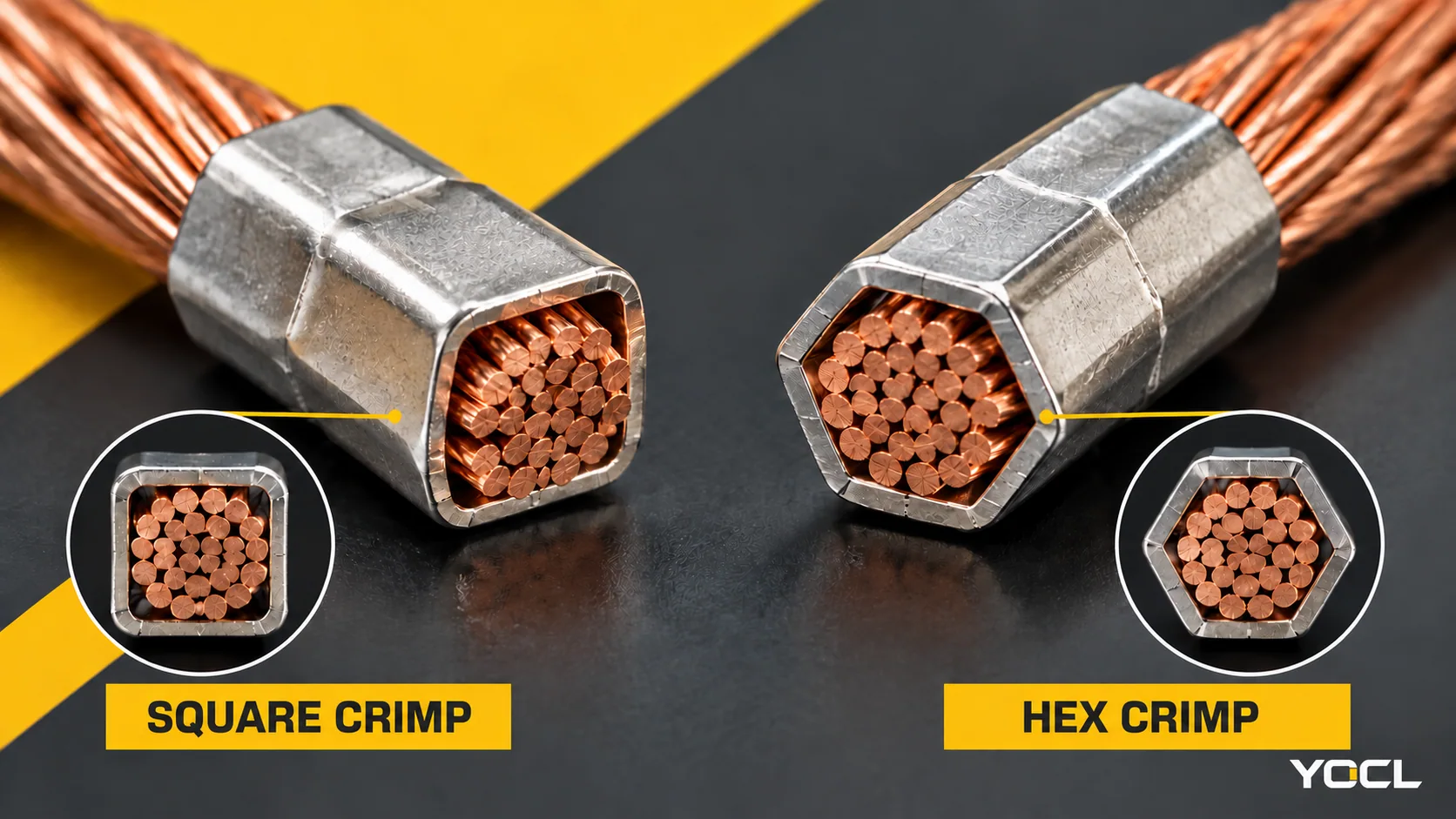
A square crimp is a sensible candidate for a rectangular terminal entry with enough corner clearance; a hexagonal crimp is a sensible candidate for a circular entry where orientation matters. Neither shape is a universal approval. Use the exact terminal’s instructions and the dimensions of the finished crimp to decide. If the terminal permits neither prepared end, or its requirements cannot be established, changing the die shape does not solve the compatibility problem.
The decision concerns the shape produced on a ferrule’s metal sleeve, not the shape of its insulating collar. It also concerns a complete connection: the wire must be correctly captured by the ferrule, the crimped sleeve must enter, and the terminal must clamp the permitted prepared conductor as intended. A sleeve that slips through the opening has passed only one of those checks.
Square or Hexagonal: Compare the Same Connection
Assume the same conductor, ferrule model and exposed metal length are being considered for the same terminal connection point. Changing the die changes the finished sleeve profile; it does not change the terminal’s declared conductor range or turn a single-wire ferrule into a twin-wire ferrule.
| Check on that connection | Square crimp: four principal flats | Hexagonal crimp: six principal flats | What actually decides |
|---|---|---|---|
| Rectangular or square entry | Flats can align with the entry; corners may obstruct a tight opening | May enter if its finished envelope and orientation fit | Actual opening, lead-in and maximum crimp width—not the shape name |
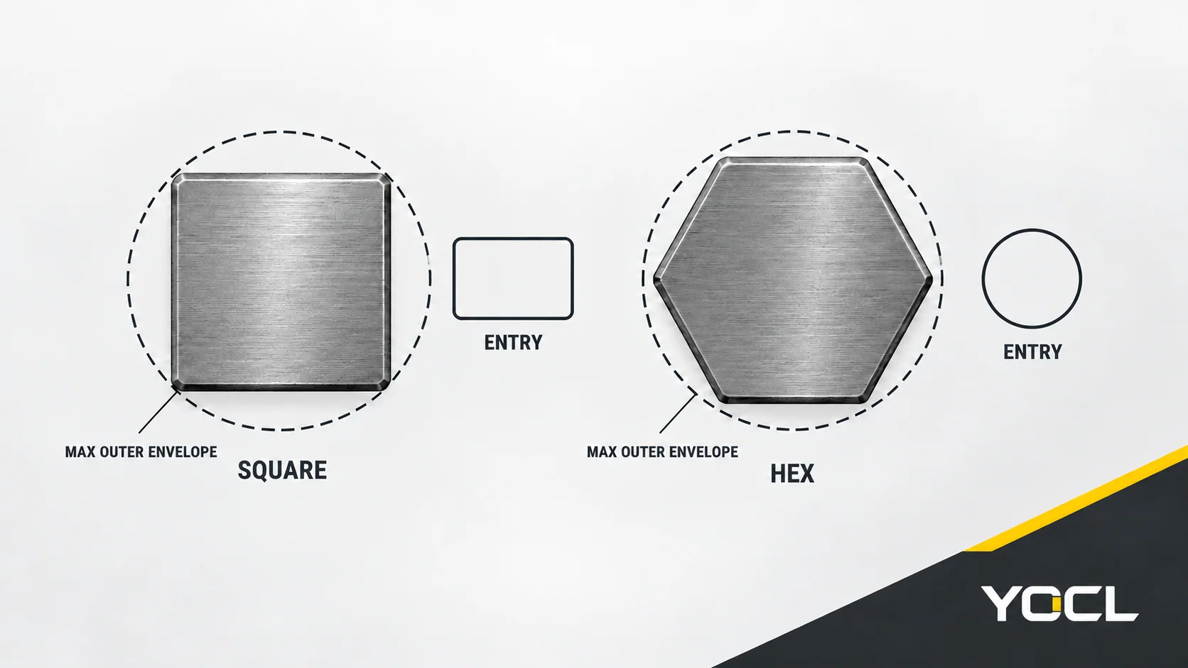
| Circular or drilled entry | Corners can set the limiting diameter, especially near the upper end of the allowed wire range | More nearly round outline can make insertion less orientation-sensitive | Maximum corner-to-corner envelope and the terminal’s permitted preparation |
| Clamp contact | A flat may face a clamping surface, depending on orientation and design | A flat or edge may face it, depending on orientation and design | Terminal construction and its documented ferruled-conductor acceptance |
| Production repeatability | Requires the specified square die and consistent final dimensions | Requires the specified hex die and consistent final dimensions | A validated ferrule–wire–tool combination and inspection process |
| Electrical or mechanical performance | Shape alone gives no performance ranking | Shape alone gives no performance ranking | The permitted connection and relevant qualification evidence |
This is a geometry-based screening table, not a list of certified terminal combinations. The intuitive “square for square, hex for round” rule is useful for choosing a candidate to check, but it becomes unreliable when an entry has a restrictive lead-in, a deep collar recess, a non-obvious clamp position or manufacturer-specific crimp instructions. Even two dies both called “square” can leave different dimensions and corner conditions.
Why the Finished Profile Matters More Than the Die Label
A ferrule starts as a thin metal tube around the conductor. A square die forms four main flats; a hex die forms six. In a simplified regular polygon, the distance across flats is smaller than the distance across opposite corners. Real crimped ferrules are not ideal polygons. Their wall thickness, seam, conductor fill, die geometry and compression affect the actual envelope.
Consequently, “2.5 mm² ferrule” identifies a nominal conductor choice; it does not tell you the finished width of every crimp made on that ferrule. Nor does an uncrimped tube outside diameter tell you the width after compression. The limiting feature can be a corner, a raised seam, an uneven mouth or the insulated collar rather than a flat face.
For fit, record the largest relevant width over the finished metal sleeve, including the angular orientation that produces the widest projection into the entry. Where a drawing uses a specified gauge or go/no-go dimension, use that method. Avoid inventing a universal square-to-hex size conversion: the two profiles are produced by different tools on deformable metal, so a nominal wire size cannot supply a reliable conversion.
Three Interfaces Must Pass
1. Wire to ferrule: a sound crimp
First confirm that the ferrule is intended for the conductor material, size, construction and wire count. Confirm that the crimp tool and die are specified for that ferrule and conductor combination. The tool must complete its intended cycle; strands should be captured, and the sleeve should not be split, visibly under-compressed or distorted at the mouth. A visually tidy square or hex outline is not proof that the wire-to-sleeve joint is acceptable.
If a ferrule is made with an unlisted tool simply to obtain a preferred shape, its resulting appearance cannot establish a qualified crimp. Do not use an extra squeeze or a second profile over a finished crimp as an improvised fit correction unless the responsible product instructions explicitly permit it. The question is whether the specified crimp system produces an acceptable end for the specified terminal.
For the basics of sleeve construction and purpose, see what a wire ferrule is. This article focuses on the interface created after that sleeve is crimped.
2. Finished end to terminal entry: a complete seat
The metal sleeve must pass through the terminal’s lead-in without shaving, folding or forcing it. The insulated collar, if present, must also clear the housing and allow the metal to reach the intended clamping zone. Compare the required exposed metal length and the terminal’s preparation or strip-length instructions with the chosen ferrule’s actual construction. A longer barrel can bottom out or leave an unwanted exposed portion; a shorter one can fail to reach the intended contact area. Neither outcome can be corrected by changing from square to hex.
Pay particular attention near the upper end of a terminal’s listed conductor range. Nominal conductor area and a claimed ferrule range may both fit on paper while the finished corner envelope or collar cannot enter the actual opening. At the lower end, easy insertion may conceal an end too small for the intended clamping arrangement. In both cases, entry fit is necessary but insufficient.
The wire ferrule size chart explains YOCL’s declared conductor sizes and exposed-barrel lengths. Use it to shortlist a model, then check its crimped profile and the receiving terminal separately.
3. Terminal clamp to prepared conductor: documented acceptance
The connection point must be intended to clamp that ferruled conductor configuration. Read the terminal maker’s permitted wire size and class, single/twin arrangement if applicable, ferrule conditions, insertion or strip length, and any specified tool or profile. An opening may accept the sleeve while the clamp does not apply pressure where expected. Conversely, a terminal may be designed to accept several finished profiles; its instructions, not an assumed shape rule, decide.
The IEC 60947-7-1:2025 official scope covers industrial terminal blocks with screw-type or screwless clamping units for copper conductors, with or without special preparation. Its public catalogue description does not prescribe square versus hexagonal ferrules for a particular terminal. A standard covering a terminal-block family is not a substitute for the chosen model’s connection instructions.
How Entry and Clamp Designs Change the Candidate
Rectangular entry. A square crimp can align its flats with the sides, but the orientation must be achievable during insertion and after the wire is routed. A hex crimp can also fit if its finished envelope clears the slot. Check the narrow dimension of the entry and its lead-in, not merely its apparent width in a photograph.
Circular entry. A hex profile often offers a more uniform outline as it rotates; it is a useful candidate when a square crimp’s corners become the limiting feature. Yet a hex has corners too, and a circular mouth can still be narrower than its maximum finished span. The metal sleeve, collar and intended insertion depth all need checking.
Screw-clamp terminal. “Screw” describes the actuation, not a guaranteed bore shape. A cage, pressure plate, drilled passage and barrier-strip screw can present different entry and contact arrangements. Check whether the screw or plate bears on the prepared end in the intended position. A broad flat-looking crimp does not authorize use under a particular screw.
Spring or push-in terminal. “Spring” likewise does not prescribe a ferrule profile. A tool-open spring clamp and a direct push-in connection may have different entry and insertion behavior. The user must establish whether the specific terminal accepts a ferruled flexible conductor, what dimensions or preparation it specifies, and whether insertion can be completed without deforming the crimp. Our screw versus spring terminal-block comparison explains the clamp-method tradeoffs; neither category alone chooses square or hex here.
These cases avoid a common shortcut: treating the visible entrance as the entire connection. A molded opening, metal contact and clamping mechanism can have different geometries. A photo of the front face rarely reveals all three.
A Practical Compatibility Decision
Use this sequence for a new terminal–ferrule combination before specifying a profile for production. It is an engineering screening and documentation method, not a replacement for the device maker’s installation instructions or qualification requirements.
- Name the exact connection. Record the terminal model and connection point, not just “spring terminal” or “2.5 mm² block.” Obtain its current instruction or datasheet and identify the permitted conductor preparation and wire range. Note whether one or two conductors may use that clamping point.
- Choose the ferrule construction. Select the documented single or twin ferrule for the actual conductor count, nominal size, material and strand construction. If the wire count is unresolved, use the single versus twin ferrule comparison first. Record the ferrule model and exposed metal length. An insulated collar can change entrance clearance even when the metal sleeves match.
- Choose the documented tooling. Obtain the ferrule/tool/die instructions. Confirm the required profile, if one is specified, and the allowed wire range. Make a representative finished sample with the specified process and inspect for captured strands, an intact sleeve and a complete crimp.
- Check the actual envelope. Compare the finished metal profile—including its largest corner span—and collar with the terminal’s entry dimensions or maker-specified gauge. If the terminal only states nominal conductor size and supplies no entry geometry, an actual fit trial is useful but cannot by itself establish approval; obtain the terminal maker’s confirmation or an applicable documented combination.
- Check seating and clamping. Follow the terminal maker’s insertion or actuation instructions on de-energized equipment. Verify full seating, the required conductive length in the clamping zone and the specified retention or inspection check. Do not use force to overcome a tight lead-in and do not infer electrical performance from a hand pull alone.
- Record the decision. Mark the combination documented only when the exact terminal’s permitted preparation and the ferrule/tool data support it and the finished end passes the prescribed fit and inspection checks. Mark it conditional while a specified dimension, test or approval is outstanding. Mark it unverified when the profile is chosen solely because it looks compatible or can be inserted.
For projects that require formal connection qualification, use the applicable product standard, device documentation and project test plan. Do not assign a universal pull force, contact-resistance value or temperature-rise limit to square or hexagonal profiles: those limits depend on the specific connection and evaluation method.
What Each Profile Cannot Fix
| Observation | Likely unresolved question | Correct next check |
|---|---|---|
| Square corners catch at a round entrance | Is the finished sleeve envelope larger than the allowed lead-in? | Measure the sample and check whether a documented hex tool/profile and terminal permission exist |
| Hex enters a rectangular slot easily | Does the clamp accept and secure that prepared end? | Read the exact terminal’s ferrule instructions and inspect the fully seated connection |
| Either metal sleeve enters, but the collar stops early | Is the collar or barrel length incompatible with the housing? | Check collar clearance and exposed-length requirements; review another documented ferrule construction |
| Ferrule fits after a second squeeze | Has the crimp process departed from the specified tool route? | Reject the improvised sample and return to the approved ferrule/tool instructions |
| The terminal is rated for the nominal wire size | Does its rating cover this ferruled wire class and wire count? | Check the exact connection configuration and applicable instructions |
| A sample resists a hand pull | Is the connection qualified electrically and mechanically for its intended use? | Apply the specified inspection or qualification method; do not treat the hand check as certification |
The table also defines a neither outcome. If neither square nor hex can be made with the specified ferrule tooling and accepted by the chosen terminal, select a different documented ferrule/terminal arrangement. Do not use a tighter crimp as a workaround for a prohibited conductor preparation.
Record the Combination, Not Just the Shape
For procurement or a panel-build work instruction, the useful record is the whole combination. Copy the following fields into the connection schedule and attach the actual supporting documents:
| Field to record | Example of the required level of detail |
|---|---|
| Terminal | Manufacturer, exact model, connection point and revision of instructions |
| Conductor | Material, nominal size, strand construction and number of wires |
| Ferrule | Manufacturer, exact single/twin model, insulation option and exposed metal length |
| Crimp | Tool, die/profile, setting or locator where specified, and instruction revision |
| Finished end | Measured maximum sleeve envelope, any specified gauge result, collar clearance and visible defects |
| Terminal acceptance | Permitted ferruled-conductor range, preparation rule, insertion method and seating result |
| Decision | Documented, conditional with missing evidence named, or unverified/rejected |
This record prevents a procurement change from silently substituting a different die or ferrule under the same nominal wire size. It also makes a failed fit actionable: the team can identify whether the blocker is the crimp, the entry or the clamp.
Within the scope of UL 486E, its public §1.4 provides a route for conductors prepared with ferrules evaluated to UL 486F, subject to the ferrules’ ratings/instructions and the equipment terminal’s exposed-conductor length requirement. UL 486E, Edition 6, public §1.4. This scoped provision does not declare square or hex universally acceptable, certify a YOCL ferrule, or waive model-specific fit checks. The UL 486F public scope also excludes use in insulation-displacement terminal blocks; do not transfer this ferrule discussion to that connection type.
If the chosen ferrule is in YOCL’s range, use the YOCL wire-ferrules product page to identify the E insulated, EN non-insulated or TE twin family. Send the exact wire specification, terminal model, required sleeve length and proposed crimp tool/profile when requesting a matching ferrule drawing or sample. YOCL’s family page itself calls for checking the tool, die and finished dimensions against the terminal entry; catalogue family names do not settle the connection decision.
Related reading: See wire-ferrule crimping procedure.
References
- IEC — IEC 60947-7-1:2025, Low-voltage switchgear and controlgear, Part 7-1. Official catalogue abstract; terminal-block scope only. Full standard not consulted.
- UL Standards & Engagement — UL 486E, Equipment Wiring Terminals, Edition 6. Public §1.4; scoped ferrule-use conditions. Full standard not consulted.
- UL Standards & Engagement — UL 486F, Bare and Covered Ferrules, Edition 3. Public scope, including insulation-displacement exclusion. Full standard not consulted.
- YOCL product information — Wire Ferrules Manufacturer, E/EN/TE families. Product range and finished-profile selection caution, accessed October 14, 2026.