
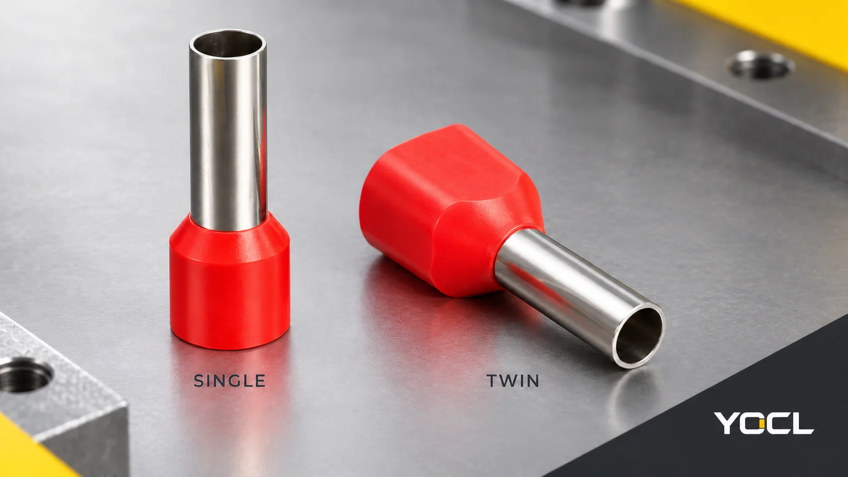
Use a single-wire ferrule for one conductor when the receiving connection permits that prepared end. Use a twin ferrule for a documented two-wire combination that can share one prepared end in the receiving connection. For two wires, separately ferruled ends may also be appropriate. The choice depends on the permitted connection arrangement, each wire’s specification and the finished end’s geometry.
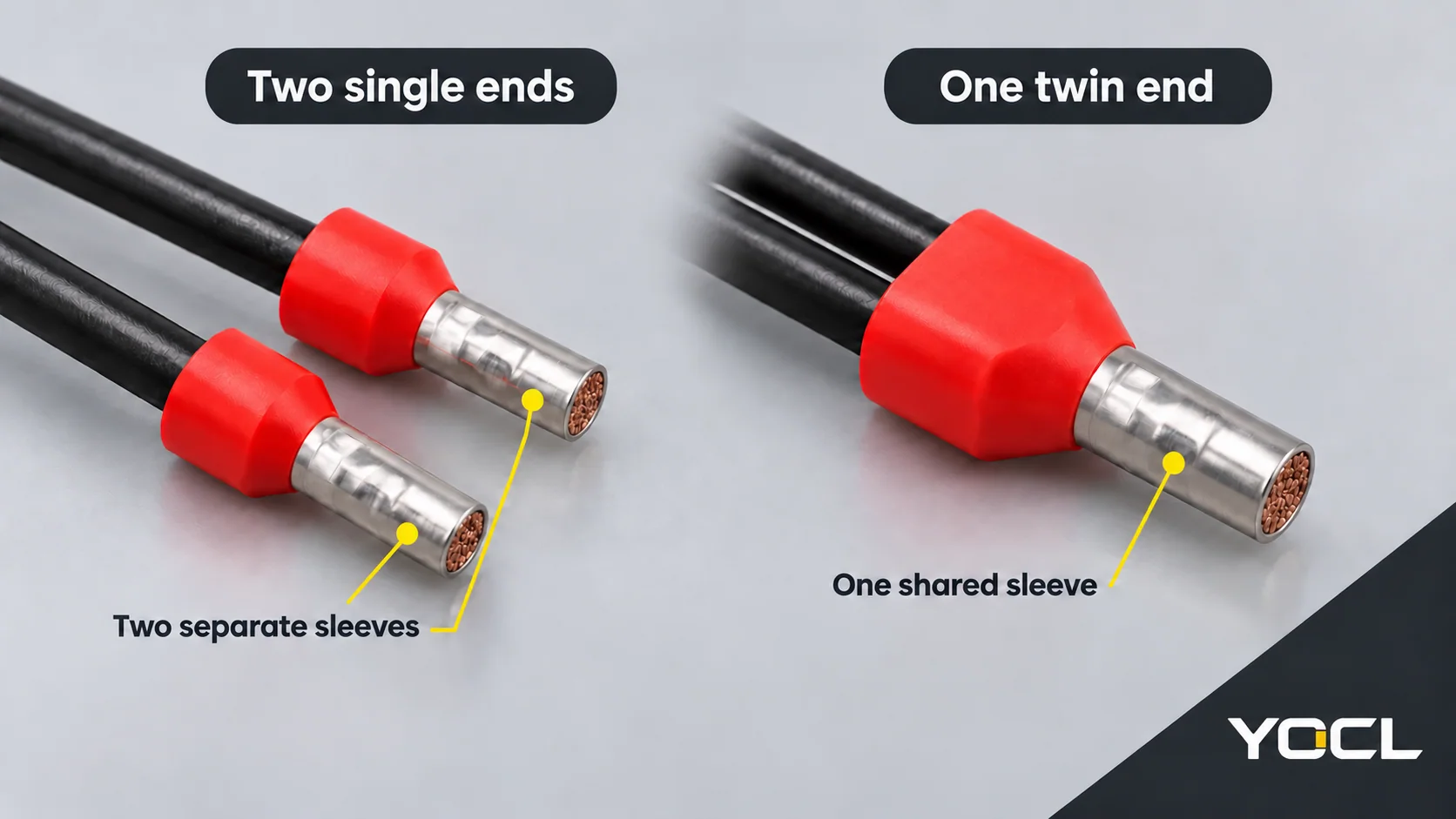
A twin ferrule creates one common prepared end. Two single ferrules create two individual ends. Those arrangements need different fit checks even when they serve the same electrical node.
Choose by the Receiving Connection
Compare the options against the same objective: terminate the specified wire or wire pair in a permitted connection.
| Wire and connection condition | Appropriate arrangement | Condition that controls the choice |
|---|---|---|
| One conductor, with a permitted ferruled connection | One single-wire ferrule | Match the conductor and prepared end to the connection requirements |
| Two conductors, each using its own permitted clamping point | Two single ferrules, one per wire | Establish the required electrical connectivity between the points |
| Two equal-size conductors sharing one common prepared end | A twin ferrule designed for that pair | Establish the applicable ferrule/terminal route and finished-end fit |
| Both separate-end and common-end arrangements are permitted | Either arrangement can be considered | Compare the actual clamping layout, profile, length and collar space |
| Two individually ferruled ends sharing one clamp | Two singles only where that configuration is permitted | Permission for one twin end does not establish permission for two separate ends |
| A mixed-size pair without supporting combination data | No common-end substitution is confirmed | Use an explicitly documented combination or suitable separate connections |
For construction and terminology, the wire-ferrule overview supplies the background. Here, the decision is which prepared-end arrangement suits the connection.
Count Wires, Prepared Ends and Clamping Points Separately
With two single ferrules, each conductor retains its own metal sleeve. The pair has two original wires and two prepared ends. With one twin ferrule, both conductors share a sleeve: two original wires and one prepared end.
A terminal assembly can have several connection points. Count the actual clamping points used, rather than assume that “one terminal” means one opening or one clamp. If separate points must form the same electrical node, confirm their documented internal connection or the applicable bridge arrangement. Adjacent terminals are not automatically connected.
Keeping the ends separate allows the arrangement to use individual clamping points. Combining them in a twin changes the end presented to a common clamping point. Neither construction removes the receiving device’s connection requirements.
Compare the Same Wire Pair: Two E1008 Ends or One TE 1008 End
Assume the connection is intended to join two 1.0 mm² stranded copper conductors at the same node. Compare two individual YOCL E1008 single ferrules with one YOCL TE 1008 twin ferrule. These are candidates for different connection arrangements, not approved substitutes.
| Comparison field | Two E1008 ferrules | One TE 1008 ferrule |
|---|---|---|
| Declared conductor arrangement | One × 1.0 mm² in each ferrule | Two × 1.0 mm² in one ferrule |
| Number of prepared ends | Two | One |
| Exposed metal length F | 8.0 mm per end | 8.0 mm |
| Overall length L | 14.7 mm per ferrule | 15.1 mm |
| Catalogue W, as labelled | 3.1 mm per ferrule | 5.1 mm |
| Uncrimped tube outside diameter D / DΦ | 1.8 mm per ferrule | 2.3 mm |
These are YOCL’s declared nominal catalogue dimensions, with letter meanings checked against each series drawing. W identifies the labelled entry dimension; it is not a complete maximum collar envelope. D describes the uncrimped tube, not the finished crimp.
Both options have F = 8 mm, yet their prepared-end count and nominal geometry differ. Two E1008 parts do not become one TE 1008 part by placing them alongside each other. The terminal still needs the appropriate arrangement, exposed length, finished profile and entry clearance. The catalogue comparison cannot confirm those conditions.
For other conductor sizes and length options, use the wire ferrule size chart rather than infer dimensions from the model-code pattern.
Match the Finished End to the Terminal’s Connection Requirements
Read the exact receiving device’s connection data and instructions. Distinguish any categories for a single ferruled conductor, two conductors in a twin ferrule, and two separate ferruled ends. A headline conductor range does not resolve which configuration applies.
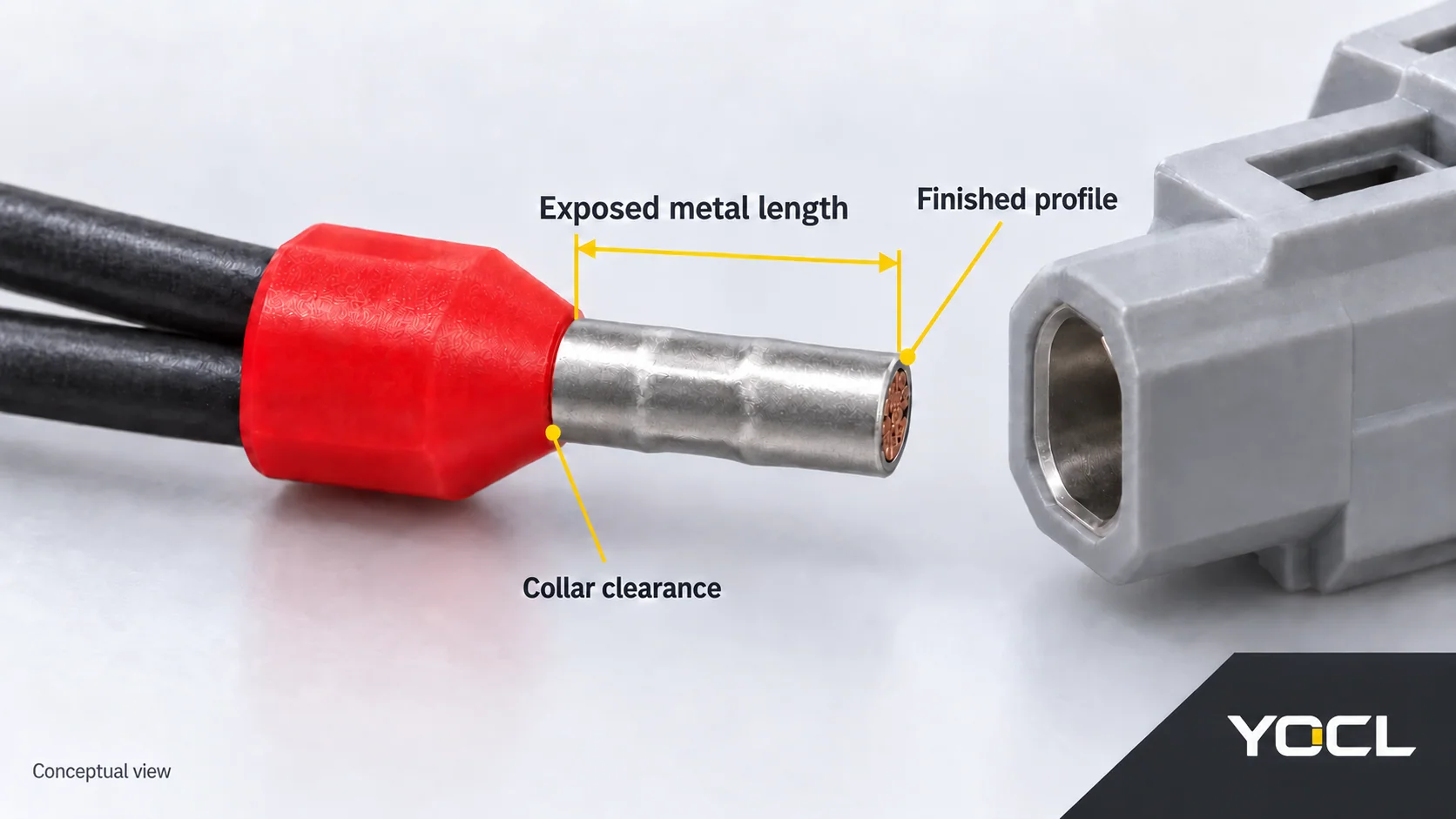
Compare the specified configuration with three physical features:
- Finished metal profile: its shape and dimensions after the applicable crimping operation. Catalogue diameter is insufficient; a square or hexagonal profile name alone does not establish fit.
- Exposed conductive length: the metal available for the receiving connection. Match the device’s preparation requirements; F and overall L are not stripping instructions.
- Collar and entry clearance: the complete collar and wire-entry arrangement around the terminal mouth. A nose that enters the opening does not prove the whole end can seat correctly.
There can be a standards-based compatibility route. For equipment wiring terminals within UL 486E’s scope, its public §1.4 permits use of ferrules evaluated under UL 486F when applied within their ratings and instructions, with exposed conductive length meeting the connector manufacturer’s strip-length requirements. UL 486E, Edition 6.
That scoped route is not a rule requiring every device to carry a separate “twin approved” label. It also does not establish that a particular YOCL model is evaluated to UL 486F or fits the chosen equipment. Record the applicable route and actual model evidence.
Equal-Size Pairs, Mixed Sizes and Summed Area
2 × 1.0 mm² means two wires, each nominally 1.0 mm². Their areas add to 2.0 mm², but this does not qualify a single-wire 2.0 mm² ferrule for the pair or establish terminal current capacity. Preserve the original conductor count and specification.
YOCL’s listed TE combinations are equal-size pairs. Within its U.S./Canadian application scope, UL 486F’s public §1.2 likewise covers one stranded copper conductor or two stranded copper conductors of the same size.
For 0.75 mm² + 1.0 mm², the sum of 1.75 mm² does not identify a matching TE equal-pair model. That mixed pair is outside the cited same-size scope and has no supporting combination data in the reviewed YOCL catalogue. Seek documentation for the exact pair, ferrule, tooling and receiving connection, or use separately suitable, permitted connection points. This evidence gap does not establish a universal prohibition on every purpose-designed mixed-size product.
Choose the Arrangement You Can Document
For the two 1.0 mm² wires, choose two singles when the individual ends and their clamping arrangement are permitted. Choose one twin when the common prepared end meets the applicable connection route and physical requirements. If both arrangements are documented, either remains an option. If only nominal ferrule dimensions are available, keep terminal acceptance unresolved.
When reviewing the YOCL wire-ferrule range, provide each wire’s size, material and construction, the intended single/twin arrangement, exposed-length requirement, terminal reference and quantities. Request the relevant model and tooling documents for that combination.
References
- YOCL product information — E Series Pre-Insulated Wire Ferrules. Published model table and original drawing; E1008 declared dimensions, accessed October 7, 2026.
- YOCL product information — TE Twin Cord End Connectors. Published model table and original drawing; TE 1008 arrangement and dimensions, accessed October 7, 2026.
- UL Standards & Engagement — UL 486E: Equipment Wiring Terminals for Use with Aluminum and/or Copper Conductors. Edition 6, January 31, 2024; public scope, §1.4. Paid full standard not consulted.
- UL Standards & Engagement — UL 486F: Bare and Covered Ferrules. Edition 3, December 9, 2024, revised August 28, 2026; public scope, §1.2. Paid full standard not consulted.