
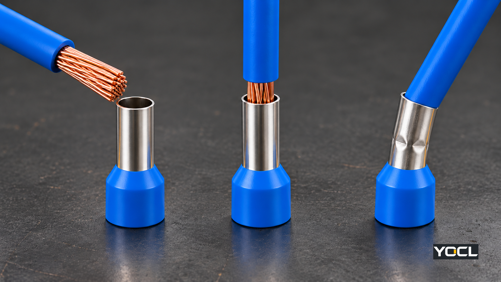
Use the documented ferrule, crimp tool and die for the actual conductor and terminal, and follow that combination’s instructions. Isolate the circuit, strip the specified length, keep every strand inside the sleeve, insert the ferrule fully, and finish the tool’s intended crimp cycle. Then check the sleeve, collar, conductor entry and finished profile. That visual inspection can find exposed strands and obvious damage; it cannot by itself prove pull strength, resistance or long-term performance.
A good result is a complete, specified process producing an end that the receiving terminal is permitted to accept and can clamp as intended. A visually neat oval or hexagon is only one observable result. Before making a production connection, establish the four links in one controlled combination:
stranded conductor → ferrule model → tool and die → receiving terminal
When any of those links is unknown, stop. Do not select the ferrule by colour alone, the die by the shape it happens to make, or the strip length by copying a number from a different model. YOCL’s wire-ferrule range introduces the E, EN and TE families and also directs users to confirm the tool, die, finished profile and terminal entry. It does not publish one universal crimp specification for all of them.
Tools, Documents and the Expected Finished End
Work on a de-energized and isolated conductor under the applicable site procedure. Confirm that the conductor is not back-fed and has been made safe before stripping or reworking an existing connection. The following article covers the mechanical preparation of one conductor end; it does not supply terminal tightening torque, reconnect checks or equipment energization instructions.
Assemble the exact documents before touching the wire. At minimum, keep the terminal’s permissible conductor range and preparation instructions, the ferrule data for the selected model, and the crimp tool or die instructions visible at the bench. Where a project controls the crimping process through a work instruction, calibration record, die schedule or qualification plan, use the current revision rather than generic website guidance.
| Input to confirm | Record or visible feature | Stop condition |
|---|---|---|
| Terminal permission | Exact terminal or connection point, accepted conductor preparation, conductor range, insertion requirement | No evidence that this ferruled conductor arrangement is permitted |
| Conductor | Stranded-copper construction, nominal size, tolerance and one or two conductors | Conductor does not match the ferrule’s declared arrangement |
| Ferrule | Exact series and model; for insulated types, collar arrangement and overall length | The selected model cannot accept the actual conductor and terminal geometry |
| Tool and die | Tool model, installed die, setting or locator, instruction revision and any required verification | Die/tool is not documented for this ferrule and conductor combination |
| Process criterion | Cycle stop, ratchet release, indicator, gauge or other stated completion/acceptance check | Required criterion is unknown or cannot be completed |
| Terminal fit | Metal sleeve and collar can reach the specified clamping zone | Entry or collar obstructs full seating, or the terminal requires another preparation |
The what-is-a-wire-ferrule guide explains the construction and single/twin distinction. Those facts support selection but do not define the crimp process. Use the wire-ferrule size chart to understand dimensional fields, then return to the exact model drawing for this wire. In particular, insulation strip length, exposed metal sleeve length, overall ferrule length and terminal insertion depth are four separate quantities.
Read the End Geometry Before Stripping
A controlled strip length must serve the complete ferrule and the terminal. It is not the same thing as the sleeve’s front length. YOCL’s E-series drawing, for example, uses F for the exposed metal sleeve and L for overall length including the insulating collar. A model such as E1508 lists F = 8 mm and L = 15 mm. Those public dimensions identify the model; they are not a universal instruction to strip 8 or 15 mm. YOCL E-series data.
A strip length calculated under the controlled instruction should normally check both ends. At the wire-entry end, enough conductor must enter beneath the collar or into the sleeve without damaging the insulation boundary. At the front, the conductor should not protrude beyond the metal sleeve into the terminal contact area unless the applicable design and instruction explicitly permit it. Confirm the actual arrangement with a sample before changing a production setting.
Two common shortcuts break the dimensional check:
- Using L as the strip length. The collar is part of L. Stripping the full overall length can leave insulation outside the intended boundary while exposing conductor where the collar should meet the wire.
- Copying a strip setting from another series. Even when nominal conductor sizes look alike, the sleeve, collar and receiving terminal can require another length. Model names alone do not transfer settings.
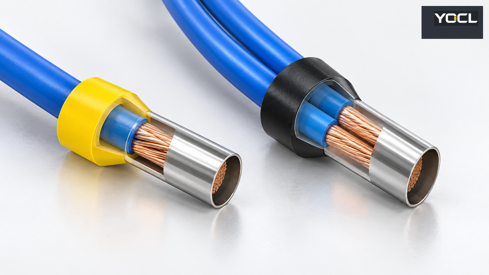
For a twin ferrule, read the size per conductor. YOCL’s TE models are described as two-conductor ferrules, so the wire count, relative strand loading and terminal permission need separate checks. A single versus twin ferrule comparison helps choose the correct arrangement; it does not authorize a terminal to take two wires.
Prepare the Strands and Load the Ferrule
1. Cut and strip the specified length
Use the controlled conductor preparation instructions and correct tool for the cable insulation. Cut the end squarely enough that the strands can be gathered, then strip the documented length without nicking, stretching or breaking strands. Start again with a fresh end if the strip process has damaged the conductor. A ferrule cannot restore cross-section that the stripping tool has removed.
Wipe or clean the conductor only if the applicable cable, ferrule and site instructions allow the method and materials. Dirt, excess compound or loose debris around the strands makes the placement check harder and should not simply be carried into the sleeve. Do not solder the strand bundle or coat it with an improvised filler as a substitute for the specified crimp: the evidence scope of IEC 60352-2:2024 concerns the designed solderless crimp barrel, and another preparation changes that process.
Expected result: the required length of copper is exposed, the insulation boundary is intact, and the strands are still equal to the specified conductor construction. If that is not visible, stop before loading.
2. Gather every strand and inspect the entry
Twist or reshape the strands only as far as the cable and ferrule instructions allow. The sleeve must encompass all strands; a group that has lost a broken strand or left a stray outside the metal tube is not a candidate for a show-quality crimp. The front mouth should be open and clear, with no folded-back strand across it.
Check that the ferrule is the exact model, free of a split sleeve, collapsed mouth or damaged collar, and suitable for the current conductor material and count. The US/Canada scope of UL 486F Edition 3 describes covered and bare ferrules intended for one stranded copper conductor, or two of the same size within its limits. That scope is a way to understand the product family in its covered market; it is neither a YOCL model listing nor a blanket terminal approval.
3. Insert until the controlled position is reached
Slide the conductor through the wire-entry opening and into the sleeve. Feed slowly enough to see the strand bundle stay together. If the ferrule has an insulating collar, do not force individual strands between the collar and metal sleeve. For a non-insulated ferrule, confirm that the flared entry or other visible feature does not collect a stray strand outside the intended tube.
Insertion is complete only when the selected instruction’s position is satisfied. A common visible check is that the strand bundle reaches the intended area without projecting out the front, but the exact model’s construction and terminal requirement decide. Do not set the final insertion depth from one generic photo. The square versus hexagonal crimp comparison begins after the wire/sleeve fit and explains that a die profile does not remedy a loading or terminal-entry problem.
Expected result: the ferrule is fully supported in the tool with all intended strands inside, its collar and mouth are undamaged, and there is no apparent gap or protruding strand. If the conductor slides out or a strand escapes, remove the ferrule and restart from a sound conductor end.
Make One Complete, Specified Crimp
4. Position the exact die where the instructions specify
Install the die or tool setting identified for that ferrule. Check the closing position before the wire is loaded if the tool’s instructions require it. A die whose jaw steps look suitable is not necessarily approved for the ferrule model, and a broad nominal wire range does not replace a ferrule/tool compatibility chart.
For a pre-insulated ferrule, the crimp region is the metal sleeve where the tool is designed to compress it. Keep the insulation collar and conductor insulation out of a jaw closing zone where they could be pinched, unless the exact tool design deliberately accommodates them. For a non-insulated ferrule, confirm that the full metal barrel is aligned in the intended die. Do not proceed if the tool has a damaged jaw, broken locating feature, missing pin or an unclear die designation.
5. Close the tool only as its process requires
Hold the loaded ferrule in the specified position and actuate the tool through the intended cycle. A ratcheting crimping tool is designed to complete a controlled cycle; follow its stated release or opening method rather than forcing it open midway. If the tool, ferrule or terminal instruction requires a different actuator, cycle or number of crimp positions, use that method exactly.
Do not add a second squeeze because the first crimp looks flatter or rounder than a reference sample, and do not apply a second die over an already formed sleeve to make it enter a terminal. An extra or combined operation changes the specified process. The IEC 60352-2 abstract highlights that crimped-connection results can be compared when tools of different designs or manufacture are used, reinforcing the need to identify the actual tooling rather than judge only from the final silhouette. IEC 60352-2:2024.
Expected result: the tool performs its documented cycle, the crimp is made at the intended position, and the jaw can be opened only as designed. If the cycle is interrupted, the ferrule moves, the tool misfires or the jaw stops short, mark the part not accepted. Do not assume that one more actuation has repaired an incomplete cycle unless the exact instruction authorizes that recovery.
Check the Result Before It Goes Into the Terminal
Inspect the finished end in good, diffuse light before insertion. Use magnification when that is part of the established work practice or a detailed feature is difficult to see. Record the observation; “looks okay” is not a traceable result.
| Observation | Pass when | Hold when | Reject / restart when |
|---|---|---|---|
| Conductor entry | Every intended strand is within the ferrule and the collar/boundary is intact | Placement is ambiguous or the indicator/gauge result is unknown | A strand is outside, a strand is missing, or the conductor does not occupy the specified position |
| Mouth and strand ends | The bundle remains contained; the instruction’s mouth condition is met | Front projection or end position cannot be compared with the exact requirement | A strand protrudes in a prohibited way, a folded bundle blocks the sleeve or the mouth is incompletely formed |
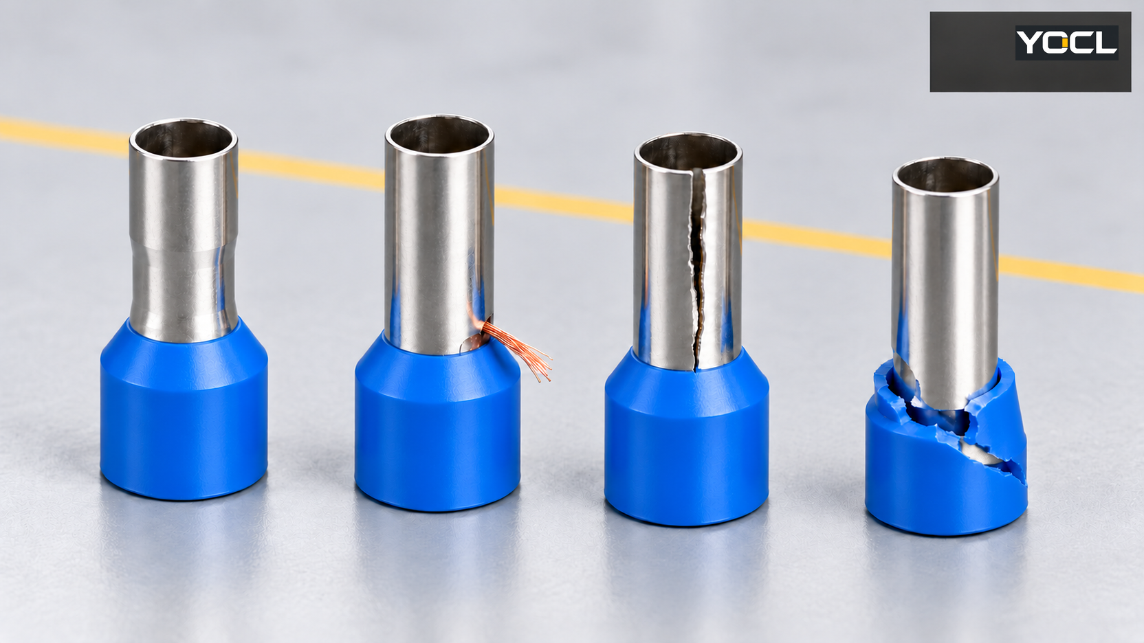
| Metal sleeve | The specified die pattern/cycle is present where required; no split, crack or loose sleeve | A mark falls outside the reference or a gauge is needed | Crease in the wrong location, loose or split sleeve, obvious under/over-crimp or missing indicated cycle |
| Insulation collar | Present as specified and not visibly cracked, cut, melted or displaced | Collar clearance or damage is uncertain | Damaged or missing collar, or insulation swallowed/pierced in a way that changes the terminal interface |
| Axial result | The finished end is straight enough to align with the terminal | Alignment cannot be judged safely or needs the terminal’s gauge | Bent sleeve, deformed collar or an end that cannot seat without force |
This table is an inspection framework, not a universal acceptance table. The crimp tool or project may define a specific reference sample, die mark, crimp width/height, pull test, cross-section or electrical test. Those criteria replace or extend the visual checks as required. A sample that looks close to another sample is not thereby acceptable if it came from a different die, tool setting or cable batch.
Do Not Repair Visible Defects With Cosmetic Workarounds
Squeezing the sleeve again, trimming a projecting strand, melting the collar flat or hiding an opened seam does not turn a rejected process into an accepted one. Remove an unacceptable ferrule in the manner permitted by the exact instructions, inspect the conductor for damage, and prepare a fresh end if any strand or insulation is compromised.
This matters in a terminal with limited entry clearance. A deformed crimp may be forced through an opening, yet that force can scrape the conductor plating, fold the collar or leave the end seated at the wrong depth. The YOCL crimp-terminal overview distinguishes a barrel connection from the terminal’s contact end; the ferrule’s tidy front does not prove the clamp beneath it receives the conductor correctly.
Check Terminal Seating and Clamping Separately
The ferrule and conductor are now one prepared end, but the connection is not complete. Insert it only into a terminal documented to accept that conductor arrangement. Follow the terminal maker’s insertion depth and actuation instructions, then make the required seating check. For a screw-clamp or spring terminal, this can involve a specific insertion path, open position, tool operation or visual window; do not infer it from the ferrule alone.
For covered UL equipment wiring terminals, the public scope of UL 486E Edition 6 section 1.4 provides one carefully limited route: ferrules evaluated under UL 486F may be used when the ferrule is applied to its ratings/instructions and the length of exposed conductive material continues to meet the connector manufacturer’s strip-length requirement. That statement does not certify a YOCL model, replace the terminal’s current instructions, or approve a finished end that fails the product checks. It does, however, show why a good crimp and a permitted terminal connection are separate approvals.
The terminal’s entry and clamp may also constrain collar and sleeve length. Follow the exact terminal’s permitted ferruled-conductor range and the required clamping position. If the prepared end enters but the terminal’s clamp does not reach its conductive zone, or if the collar prevents full seating, stop. Do not shorten the sleeve, remove the collar or insert the insulated section into the clamp as a field fix unless the terminal documentation explains a permitted alternative preparation.
What a Visual Check Cannot Prove
A visually intact crimp can still be mechanically or electrically unsuitable. IEC’s IEC 60352-2 scope covers evaluation under specified mechanical, electrical and atmospheric conditions and compares results across tool designs. That is the point at which a defined test method or qualification plan becomes relevant. IEC 60352-2:2024.
The table below separates the question being asked. Use it to request the right evidence; do not fill missing values with a rule of thumb.
| Question | Useful pre-insertion check | What may actually answer it |
|---|---|---|
| Were all strands captured? | Inspect entry, front and sleeve with magnification; use a defined gauge when specified | The project’s inspection method and any required section or strand-combination check |
| Did the crimp complete? | Confirm die, cycle and visible process mark where the tool defines it | Tool instruction, calibration/verification record and applicable acceptance criteria |
| Will it hold mechanically? | Remove obviously loose or deformed samples from the process | A specified pull/secureness evaluation using the controlled sample, method and acceptance value |
| Will it provide a stable electrical path? | Confirm the end can seat without force and the terminal accepts the preparation | The applicable resistance or other electrical test from the product/project standard |
| Will it stay acceptable in service? | Check materials, collar and the procedure’s complete range | The specified environmental/endurance evaluation and the exact service conditions |
Do not perform an improvised “pull” on an installed conductor or energize a failed sample to see whether it works. The crimp-terminal overview can distinguish the barrel and contact side, but formal current, voltage and connection ratings belong to the exact product documents. If the terminal’s current instructions are unavailable, the correct result is hold, not a guess from nominal wire size.
Record the Complete Crimp, Not Just “Pass”
For repeat work, keep a connection schedule that allows another technician to reproduce the result. Record the exact terminal model and connection point, conductor material/size/strand construction, one or two conductor arrangement, ferrule series/model, metal sleeve length F, overall length L, tool/die or setting, instruction revision, strip length and the actual inspection outcome. For twin ferrules, record the size of each conductor rather than their sum.
The single versus twin ferrule guide and size chart help complete the model fields. Pair the square and hexagonal crimp comparison with the terminal instructions when the finished profile affects entry. A production change in die, ferrule, conductor supplier or terminal revision deserves a fresh validation rather than reuse of the previous photo as proof.
YOCL’s E Series Pre-Insulated Wire Ferrules can provide the model’s conductor and F/L dimensions, while the wire-ferrule range routes E, EN and TE selection. When requesting a review, send the exact conductor and terminal references, required sleeve length, proposed tool/die and any inspection or qualification requirement. The supplier can match the ferrule data to the application, while the terminal maker must still confirm that the receiving connection accepts the finished prepared end.
References
- YOCL product information — Wire Ferrules; E/EN/TE range and declared conductor, sleeve, tooling and terminal-fit selection factors.
- YOCL product information — E Series Pre-Insulated Wire Ferrules; model dimensions including F and L, conductor range and selection declaration.
- IEC — IEC 60352-2:2024, edition 3.0; official abstract for solderless crimped connections and specified mechanical, electrical and atmospheric evaluation. Full paid standard not consulted.
- UL Standards & Engagement — UL 486F, Edition 3; public scope for bare and covered ferrules, conductor arrangements and exclusions. Full standard not consulted.
- UL Standards & Engagement — UL 486E, Edition 6; public scope of equipment wiring terminals and section 1.4 conditions linking terminal use to applicable ferrule instructions and exposed-conductor length. Full standard not consulted.