
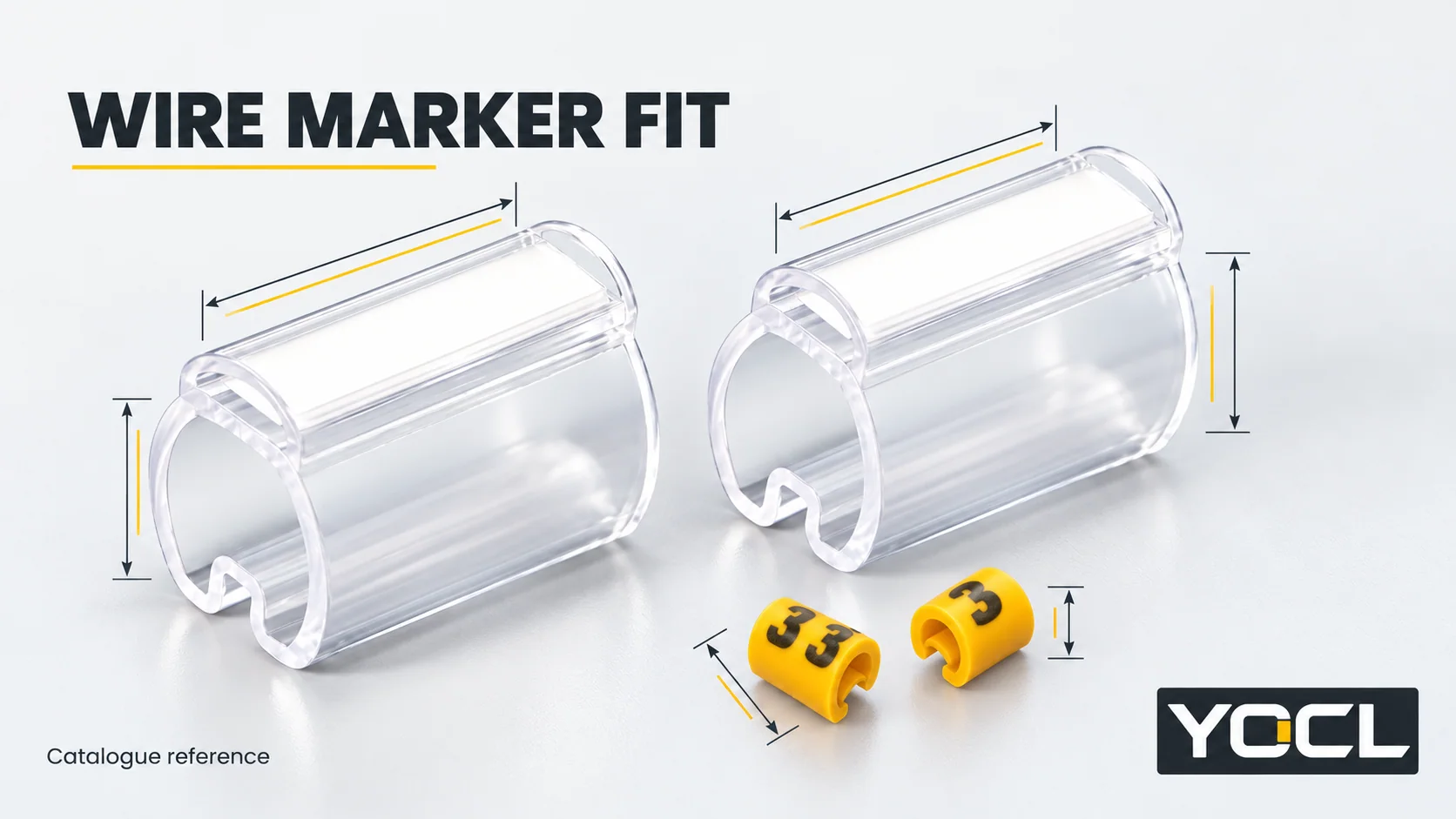
Use the conductor cross-section and the actual insulated-wire size in the same model row. For YOCL’s 201–205 sleeves, the separately listed maximum cable diameter does not extend the recommended fit range. The tables below reproduce current YOCL model fields, checked November 2, 2026; they are catalogue screening data, not a universal marker-size standard or a tested fit on your wire.
201–205 cable marker sleeve size chart
Source: YOCL 201–205 cable marker sleeves. Both diameter columns use millimetres; conductor area uses square millimetres.
| Model | Recommended conductor cross-section (mm²) | Recommended cable outer diameter (mm) | Maximum cable diameter (mm) |
|---|---|---|---|
| 201 | 0.25–1.5 | 1.5–3.0 | 5.2 |
| 202 | 0.5–2.5 | 2.0–4.0 | 6.5 |
| 203 | 2.5–10.0 | 4.0–7.0 | 8.2 |
| 204 | 6.0–16 | 5.0–8.0 | 10 |
| 205 | 25–35 | 8–12.0 | 13.5 |
Keep all three fields attached to the model. The maximum column is neither a guaranteed gripping range nor a sleeve inside-diameter specification. If the wire falls outside a recommended field, record the mismatch and request model-specific confirmation instead of accepting it from the maximum alone.
MEC round cable marker size chart
Source: YOCL MEC round cable markers. The source calls the second size field “Suitable wire size (mm)” and directs selection using insulated-wire dimensions. That field is separate from conductor area; it is not a maximum-opening column.
| Model | Suitable conductor cross-section (mm²) | Suitable wire size (mm) |
|---|---|---|
| MEC-0 | 0.75–1.5 | 2.0–3.2 |
| MEC-1 | 0.75–3.5 | 3.0–4.2 |
| MEC-2 | 3.5–8.0 | 3.6–7.4 |
| MEC-3 | 5.2–10.0 | 5.2–10.0 |
No separate maximum cable-diameter field is published for this series. Do not transfer one from the 201–205 table. Similar numerical values, overlapping intervals or model suffixes do not make the two series equivalent.
Identify the wire dimension before looking up a model
Conductor cross-section describes the conducting material in mm². Insulated-wire outside diameter includes the insulation and is expressed in mm. The marker contacts the outside profile; the conductor-area entry cannot supply that profile by itself.
Use the actual wire specification and relevant production dimensions at the marking position. If checking a sample, follow an appropriate measurement method without deforming soft insulation; record its identity and the dimension used. An assumed insulation thickness can turn a correct conductor-area value into the wrong fit decision.
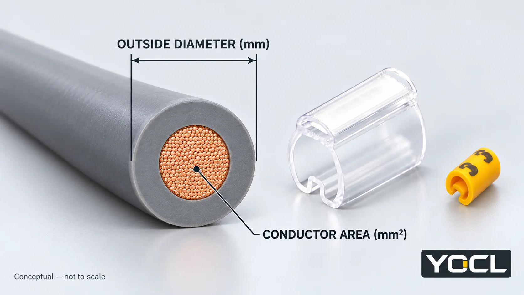
For a flat or irregular profile, provide its width, thickness and shape. A round-wire table does not automatically establish fit on that profile. Where wire dimensions vary, consider the specified variation rather than approving a model from one favorable sample. These product tables do not publish a universal fitting tolerance or a measurement allowance.
Worked lookups: reject the mismatched row
The following wires are hypothetical inputs for reading the tables, not YOCL test results or installation recommendations.
Example 1: 8 mm² conductor, 7.5 mm insulated outside diameter
| Sleeve candidate | Conductor-area check | Recommended-diameter check | Screening result |
|---|---|---|---|
| 203 | Within its listed interval | Outside its recommended interval | Do not approve from the separate maximum value |
| 204 | Within its listed interval | Within its recommended interval | Candidate for model-specific fit confirmation |
This comparison uses both fields from each row. It does not establish retention, fitting method or service suitability. A maximum value is not permission to disregard a recommendation.
Example 2: 2.5 mm² conductor, 3.8 mm insulated wire size
| MEC candidate | Conductor-area check | Wire-size check | Screening result |
|---|---|---|---|
| MEC-1 | Within its listed interval | Within its listed interval | Candidate for fit confirmation |
| MEC-2 | Outside its listed interval | Within its listed interval | Diameter agreement alone does not resolve the mismatch |
Do not borrow the conductor field from one row and the wire-size field from another. If two rows satisfy all published inputs, record both as candidates and confirm the applicable profile, fit and identification requirements. There is no automatic “choose the larger number” rule.
Other marker series: which size fields are still needed?
The public catalogue does not provide the same dimensions for every marker family. Keep missing data visible rather than manufacturing a single conversion chart.
| Series or format | What the current page provides | What to obtain before a diameter-based selection |
|---|---|---|
| EC PVC markers | Model and packaging entries; no numerical insulated-wire acceptance band | The selected profile’s insulated-wire size range and fitting information |
| SM clip-on markers | Model-specific conductor cross-section and American Wire Gauge (AWG) fields, without an insulated-wire diameter band | Actual jacket/profile acceptance and seating information; do not calculate it from conductor area |
| Heat-shrink cable markers | Sleeve-format product information, without a supplied/recovered diameter table | The selected marker’s size specification and recommended cable application range |
For these pages, missing numerical data means the diameter-based decision remains pending. It does not mean the marker fits every wire or that a similarly named model in another family supplies the answer. A general tubing size chart also cannot establish a printable marker’s supplied format or application range.
Confirm the candidate without turning the table into an installation rule
Once a row passes the dimensional screen, confirm it on the intended wire using the selected model’s fitting information. Assess whether the profile seats as specified and whether the installed legend can be read. A sample that can be forced onto the wire does not, by itself, establish appropriate retention or long-term suitability.
Near a boundary, request the applicable acceptance information rather than rounding a measured diameter into the range. Do not stretch, slit or otherwise modify a marker to make the numbers appear to agree. If the wire is already terminated, the available fitting route is another constraint; the clip-on, slide-on and heat-shrink comparison addresses that separate access decision.
The cable marker overview maps the formats and identification context. This reference supplies size candidates; it does not qualify a print system, specify recovery heat or replace the project’s identification scheme.
Keep fit data in the repeat-order record
Record the series and model together with conductor area, insulated-wire dimensions, wire reference, source-table revision or check date, and the outcome of sample confirmation. Add the required characters or complete legend and quantity separately. Pieces per bag or roll describe packaging, not the wire diameter the marker accepts.
For a fit review through the YOCL cable-marker range, send that record and identify any unmatched or unavailable field. This lets the next review address a specific size question rather than choosing from a conductor size alone.
Related reading: See YOCL resources.
References
- YOCL product information, 201–205 Cable Marker Sleeves—five model rows, separately defined recommended and maximum diameters, and source image; checked November 2, 2026.
- YOCL product information, MEC Round Cable Markers—four model rows, conductor-area and wire-size fields, and source image; checked November 2, 2026.
- YOCL product information, EC PVC Cable Markers—published model/packaging fields and size-data boundary; checked November 2, 2026.
- YOCL product information, SM Type Clip-On Cable Markers—published model fields without an insulated-wire diameter band; checked November 2, 2026.
- YOCL product information, Halogen-Free Heat Shrink Cable Markers—public specification scope without a supplied/recovered diameter table; checked November 2, 2026.